This thread has been locked.
If you have a related question, please click the "Ask a related question" button in the top right corner. The newly created question will be automatically linked to this question.
Hi,
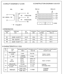
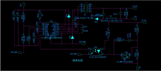
My customer is using LM5015 in a two-switch Flyback circuit, part of the schematic is as following figure. Output 5V and Input is 24V.
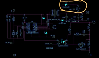
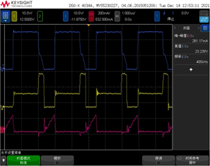
The problem they are facing is: when in DCM mode and 2 Mosfets are both turned off, Vds of two Mosfets is not the same. Yellow line is the Vds of upper Mos and red one is the Vds of lower Mos. With Diodes D30 and D36, the waveform shows as in figure 2, without diodes as in figure 3.
Could you help me to explain:
1. Why the Vds of 2 Mosfets are not the same as (Vin+Vf)/2 when working in DCM and all Mosfets are turned off ?
2. Why there are a difference when adding 2 diodes but the Vds are still not the same ?

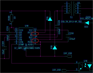
Figure1 schematic LM5015

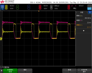
Figure2 with diodes D30 and D36 yellow: upper Vds; red: lower Vds

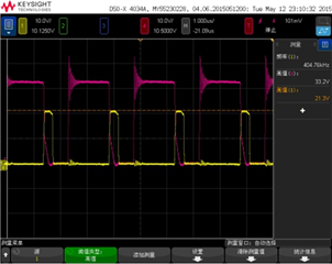
Figure3 with diodes D30 and D36 yellow: upper MOS Vds; red: lower MOS Vds
Manu Chang
Hello Manu,
In CCM, you would expect to see the voltage shared equally between the power mosfets. Source
Can you provide me additional information on the input voltage for which these tests where performed, the turns ratio of the transformer and its datasheet, and the full schematic for LM5015? Many of the components connected to the device are cropped out. I believe this information should help me better answer your question.
Hi Marshall,
Thanks for your reply, the following are the datasheet of transformer and full schematic of this circuit. turns ratio is 10:6 between N2 to N3.
Hope that this can help you.


Thank you, I did a first pass inspection on duty factor and reflected voltage and it seemed to be OK. The schematic you shared is low-resolution and I am having difficulty making anything out, Can you share with me a higher resolution schematic?
Hi Marshall, the clearer photo of schematic is as above, and the elements in yellow circle are not using so can be ignored, thanks.
Thanks, Manu. I am going to check with a colleague of mine whom has more experience with this topology/device and see what he thinks.
Hello, it does seem like this is odd behavior to my colleague as well.
The datasheet of the transformer does not specify the saturation current of it. The saturation current should be confirmed to be greater than ec specification ILIM.
In addition, I would ensure the transformer is wired up/assembled correctly.
Lastly, what is the voltage rating the rectifying diode (on secondary)? That is something which may be too low which is causing this issue.
Hi Marshall,
The transformer is wired up and assembled correctly and the saturation current is also ok.
For the third reason, could you pls kindly explain the theory that how the low voltage rate of rectifying diode can cause this scenario ?
Hello Manu,
What is the saturation current?
The waveforms look unexpected and not normal, so I am looking for components which may have been improperly selected.
We figured it would be worthwhile checking the output rectifying diodes. If we find their power rating to be insufficient I can give an alternative selection.
Hi Marshall,
The saturation current cannot provided by the vendor, but here are the waveform in this situation, which can show that current is below the saturation current of the transformer. Also the diode datasheet is provided as follows, pls kindly check and explain if there are any problems about the device selection, thanks !

Blue: Vds of upper Mos, Yellow: Vds of lower Mos
Red: primary current waveform

Diode datasheet on secondary side
Manu Chang