This thread has been locked.

If you have a related question, please click the "Ask a related question" button in the top right corner. The newly created question will be automatically linked to this question.

LM5034: Design help for 500W application

Genius 14579 points
Part Number: LM5034

Hi Experts,

Good day. Seeking for advise on this query:

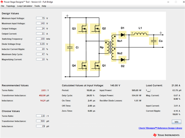
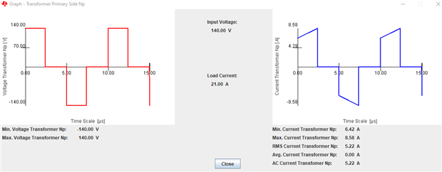
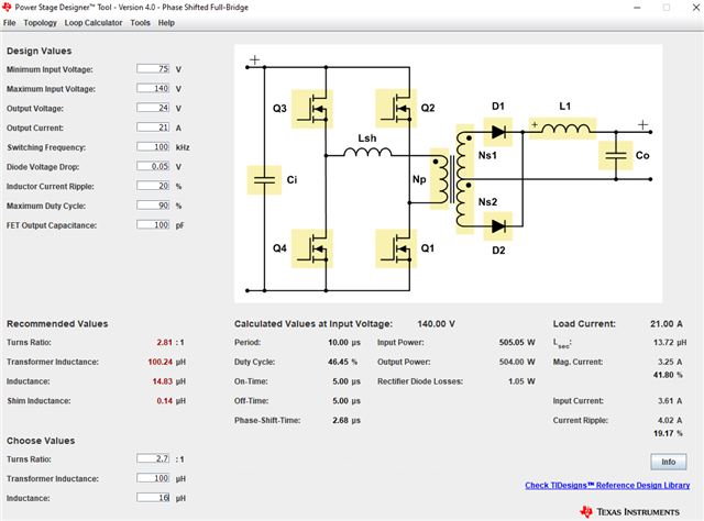
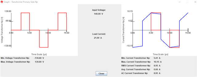
I'm designing a power supply for a rail application. Input voltage range is 75-140Vdc and output isolated 24V, around 500W and possibility for load sharing. First, was planning to use interleaved AC-Forward converter and use LM5034. I have used that controller a lot before when i worked with telecom industry. But when i tried your webench , only recommendation was LLC half-bridge. I made some calculations and i'm a little skeptical because input currents would be very high.

Please advise. Thank you.

Regards,
Archie A.

  • Hi Archie,

    Unless you're willing to pre-regulate the input voltage, LLC is probably not the best choice since your input voltage is nearly 2:1. You're input is low enough that a push-pull converter could be an option but you need to study the input current since the output power is somewhat high at 500W. If the input current seemed high for LLC, then it will probably also be high for a push-pull. 500W can easily be met with a full-bridge topology. Since your input voltage is low, input current is high you need to consider which is best between traditional hard-switched full-bridge vs phase shifted full-bridge.

    A quick comparison is shown below. 

    Hard-Switched FB:

    PSFB:

    The primary current I highlighted in the red box is circulating in the PSFB primary during the time the input is clamped (passive mode) and is quite high. A hard-switched FB does not operate in a passive clamped condition like a PSFB. Does the I^2*R loss due to this circulating primary current negate the benefit of ZVS achieved by using the PSFB? If yes, then maybe a hard switched FB is the best approach?

    The above simulations were completed using TI Power Stage Designer which I recommend as a first approach for evaluating power stage topologies as well as snubber design and control loop compensation modelling.

    Regards,

    Steve M

  • Hello Steve,

    Thanks for the detailed explanation.

    Refer below for the ff. response by the Cx:

    "Yes I have used power stage designer. At start i consired  LLC,  full-bridge and forward.

    I have now already made proto boards using  interleaved active clamp forward converter with LM5034.

    This is very familiar topology and pwm-controller,  i have used it a lot when designing power supplies for telecom equipments, 48V input and low voltage outputs, up to 200W.  I think it works quite well with this application. Maybe not the smallest but it’s not critical here.

    Almost all tests are allready made and  everything seems to be ok. Only concern is primary mosfets, i have now 250V fets and max ds voltage is  at worst case around 210V, 300V fets is a little bit more difficult to find. And transformer design is not final yet. I have to still testi if it’s more efficient with a small air gap, so to increase magnetizing current  and decrease turn on losses on FETs."

    Thank you.

    Regards,
    Archie A.

  • Archie,

    Cx response is much different compared to the original post. The original post was asking for help with a topology but the most recent response indicates a prototype design has been built with LM5034. Sounds like no additional help is needed. I will close this thread and feel free to open another if more help is needed.

    Regards,

    Steve