This thread has been locked.

If you have a related question, please click the "Ask a related question" button in the top right corner. The newly created question will be automatically linked to this question.

TPS54160: About switching frequency setting of split rail power supply

Part Number: TPS54160
Other Parts Discussed in Thread: TINA-TI,

I designed the Split rail power supply with reference to the application report below.
SLVA369A (Create a Split-Rail Power Supply with a Wide Input Voltage Buck Regulator (Rev. A))

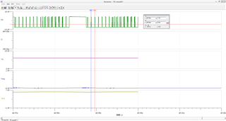
I simulated the designed circuit with Tina-TI, but it does not work as designed.
The switching frequency does not match the design.

RT was decided with reference to Equation 38 of SLVA369A.
RT (kΩ) = 206033 / 718kHz ^ 1.0888 ≒ 160kΩ

Design specification:
Vin: + 12V
Vopos: + 6V
Voneg: -6V
Iopos: 0.5A 
Ioneg: 0.3A 
Fsw: 718kHz

I attach the schematic and waveform.
Please teach me.TPS54160_split_rail.TSC

  • Hello, I tried to run your TINA schematic, but it just hangs when selecting transient analysis.

    How are you running the schemaitc and is the .tsc file shared the latest? If you have any captures of the simulaiton run I can evaluate that.

    I am unsure on the waveforms you attached. The .tdr extension is unfamiliar to me and I dont know how to view.

    You quote a load current specification of 5A and 3A. I dont see that is being feasible for the device. Is that a typo?

    Note equation 10 in the attached appnote For a load current of 5A and 3A you would be hitting the peak current limit of the device.

  • hello.
    Thanks for the reply.
    (1) The load current is a typo. Actually, Iopos = 0.5A, Ioneg = 0.3A.
    (2) Follow the steps below to open the .tdr extension.
    tool-> Diagram window (Shift + Ctrl + D)
    When the diagram window opens, run File-> open to open the .tdr extension.
    Looking at the waveform, the switching frequency is about 1.1MHz. (Even though I set it to 718KHz)
    (3) About the case where the simulation hangs.
    Attach a capture of the analysis options.
    Although it is a Japanese version, I think the arrangement of items is the same as the English version.
    Simulation time is about 35ms. (It will be in a steady state in about 30ms.) I don't know why, but it will be longer than the SS time set by the capacitor connected to SS_TR.

    I found the following description in the reference design of the URL below.
    www.ti.com/.../slim198

    TEST BENCH DESCRIPTION:
    8. The GND pin of the device is actually node 0. So, do not attempt to connect it to non-zero voltages.

    The split rail connects the device GND to a negative voltage. Does this mean that the split rail configuration cannot be simulated with this simulation model?
    Is it the cause of the problem that a voltage other than 0V is connected to the GND of the device?

    Please teach me.

  • Hello,

    I am still having issues running your simulation files. I let the simulation run for several minutes without a computation progress.

    Slim198 runs fine, so something is either getting corrupted or the settings are incorrect.

    I am not aware of any issues with the Rt calculation. I confirmed via webench that Rt=162kOhm is for 710kHz switching frequency.

    If you could share a picture image of the simulation result, I can review those to confirm they are stable.

    My speculation is, you located a bug in the TINA model. I would trust Rt=162kOhm for 710kHz switching frequency.

  • hello.
    Thank you for your reply.
    We will share the image of the simulation waveform.

    The simulation is horribly time consuming. I left it for 5 or 6 hours and it was finally over.
    For the simulation settings, I referred to the following items described in Slim198a ...
    SIMULATION INFO:
    1. Go to Analysis >> Options and Enable the option'disable warning for large size analysis'.
    2. Go to Analysis >> Set Analysis Parameters. Choose Default Analysis parameters.
    3. Go to Analysis >> Transient. Ensure that'Draw excitation' check box is unchecked.
    4. Enable'Calculate operating point'.
    5. Ensure the integration method is'Gear' and the order is '2'.
    6. To run simulation, click OK.
    7. The simulation runs for 1.2ms and takes approximately 14 mins on a 4 core 2.8GHz machine.
    8. Go to Tools >> Diagram Window to view waveforms.

    The time to reach steady state did not improve even if the SS capacitor capacity was reduced.

    >> My speculation is, you located a bug in the TINA model. I would trust Rt = 162kOhm for 710kHz switching frequency.

    → Is it better to verify the split rail on the actual machine rather than on the simulation?

    Thank you.

  • Hello,

    Your simulation doesn't look stable. I believe the best path going forward is going through the theoretical calculations and then proceeding with bench evaluation. I completed the excel calculator for this design.

    It seems the compensation componets you calculated for are off from what the calculator suggests.

    i would recommend revising to the calculator suggestion. I can review your calculations if you feel differently.

    I attached the design calculator I worked up for this design.7674.SWIFTPOSNEG-CALC-v4.xls