


Other Parts Discussed in Thread: TPS54335A, , TPS54260, TPS54302, TPS54202, TPS62933
I found some difficulties while designing compensation loop.
In the datasheet the information to calculate the values are missing.
The hint in the E2E forum (e2e.ti.com/.../tps5405-vsense-and-compensation-pin-design-guidance, using the equations from TPS54335A Datasheet for this calculation is also insufficient because the values required in the formulas are missing.
The next hint in ESE forum "TPS5405 calculations error" (e2e.ti.com/.../tps5405-calculations-error shows similar difficulties.
I also tried to use the design procedure described for TPS54260 with the mentioned parameters from John Tucker for TPS5405 (gmea = 92 umho. gmps = 9 A/V and Vref = 0.8 V), but still some parameters are missing.
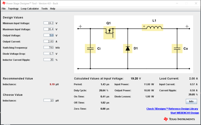
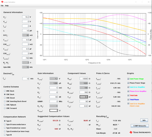
The next way I tried was using PowerStage Designer Tool 4.0 with the parameters mentioned above. Nevertheless still some relevant parameters are missing to calculate Rc and Cc.
Rs (Current Sense Resistor): no parameter in datasheet, but this parameter is relevant for result
Rfbt (Top Feedback Resistance): no parameter in datasheet for the integrated feedback divider, but this parameter is relevant for result
My question now is.
Can you provide a spice modell for TPS5405 or as an alternative the parameters to calculate the compensation loop with PowerStage Designer Tool 4.0.
or preferred from my side
adding TPS5405 in the WEBENCH power designer.
My design is 24V Input, 5V Output. 0.4-2A current output and I preferred TPS5405 because of competitive price and spread spectrum feature.
I'm wondering about the quality of TPS5405 documentation. This seems far away from what is TI standard.
Or is TPS5405 not intended for general use ?
