This thread has been locked.

If you have a related question, please click the "Ask a related question" button in the top right corner. The newly created question will be automatically linked to this question.

TPS92360: Inductor calculation method according to the datasheet (TPS92360)

Part Number: TPS92360

Hello,

I've designed a boost controller for a backlight with this part number following the datasheet recommendations.

Vin = 3V (min), 3V3 (nominal), 4V (max)

Vout = 16V min, 19,8V max (backlight)

Io = 15mA

Fsw = 1,5MHz.

Efficiency = 90%.

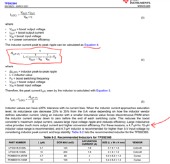
The fact is that with the formula indicated in Equation 4 (page 12) and according to my converter specifications I get 70uH (ripple 30% assumption), approximately.

That's just the Ohm's Law.

This is a very big inductor value which simply does not matches the suggested inductor specified in the datasheet of 4,7uH to 10uH, page 12, as a rule of thumb.

Am I missing something? Any ideas about it? Shouldn't both match, should it?

Could you please describe in depth how do you get the value of the inductor in the example of the datasheet?

I just expected to get the inductor value which would satisfy this criteria.

Regards,

  • hi Aaron
    that is a quite good question. I've also calculated needed inductance based on inductor current ripple requirement, your calculation is correct. The thing is that output current in your case is quite small (10mA), which means a large inductor is needed to enter CCM mode and then obtain small ripple current.

    But as you can also observe that 4.7uH-10uF is recommended, the reason is there is right half plane zero(RHPZ) for boost topology
    and increasing of inductor will decrease frequency of RHPZ, too large inductance may cause system instability.


    Obviously, system stability has higher priority than ripple current. I recommend to put 10uH inductor and 4,7uF output capacitor to
    reduce ripple.

  • Hello Mason,

    That's make sense for me now, understood.

    In fact, I designed some other Boost Dc-Dc converters using other TI devices and realized about the impact of increasing inductance vs system stability, which lead me to reduce inductance and recalculate output capacitor. But I didn't expect this to happen here again, LOL!

    I also tested with some other inductance values and saw DCM / CCM modes, which is normal as you have stated.

    Thank you very much, really appreciate your feedback.

    Regards,