This thread has been locked.

If you have a related question, please click the "Ask a related question" button in the top right corner. The newly created question will be automatically linked to this question.

TPS61176: Boost and output turns off when PWM duty is greater than ~60%

Part Number: TPS61176

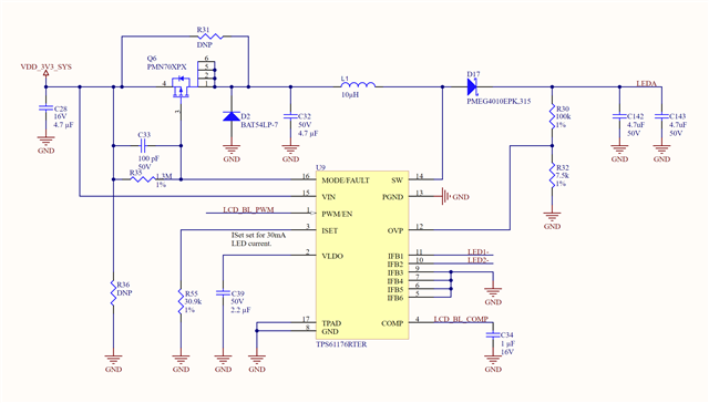
In the previous revision of our design we did not have the protection (PMOS) circuit and the MODE/FAULT pin was simply pulled to GND through a 1.3M resistor. In that original version the part behaved as expected.

The PWM signal is a 1.8V level (true for both revisions) and we would generally just drive it high to 1.8V for full brightness. In this new revision, we added the protection (PMOS) circuit but otherwise left everything the same. Now when we drive the PWM duty higher than ~60% the boost and LED outputs turn off as if we set the EN to 0. We have tried low and high frequencies (200Hz and 16kHz) for the PWM signal but the behaviour remains unchanged. The parts we are using are from the same batch for both revisions. The latest revision circuit diagram is provided below.
  • hi 

    would you mind sharing the voltage of VLED?

    is it available to provide the waveforms of pin Mode/Fault, pin SW, VLED, ILED,IFB pin under ~60% brightness. I'd like to see the details under that condition. Pls provide two separate waveforms.(one with pin Mode/Fault, pin SW, ILED) (another with pin Mode/Fault, VLED, IFB pin), zoom in would be helpful if available.

  • The LEDA signal (LED voltage supply) is 21.3V.

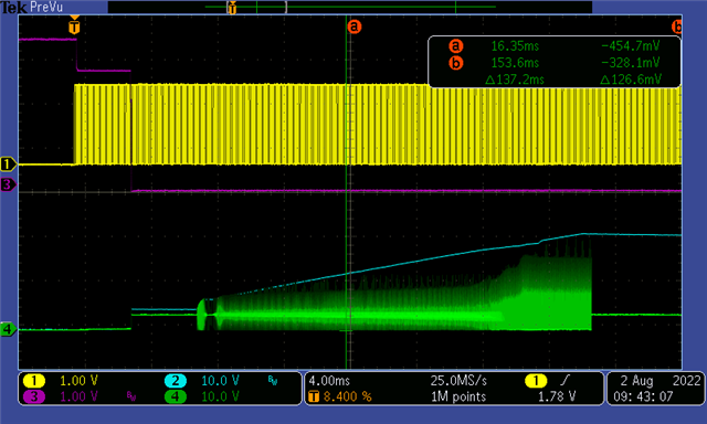
    I am working on getting these waveforms and thought I would post some that I can capture easily now.  The image below shows the MODE pin (trace 3), PWM/EN pin (trace 1), LEDA signal (trace 2) and the SW pin (trace 4). In this capture the PWM /EN signal is set to a duty of 80%. You can see the MODE pin checking the configuration at the start and then the boost switching starts. Once the LEDA voltage is obtained the boost switching stops and never starts again.

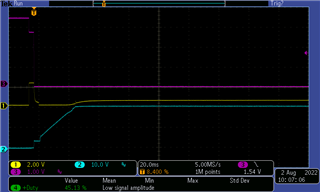
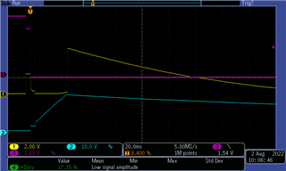
    The following two captures show the MODE pin (trace 3), LEDA signal (trace 2), and the IFB pin (trace 1) of one of the LED outputs. The first capture shows the start condition with the PWM/EN signal is set to 50% duty. The second capture shows the same signals but with the PWM/EN signal set to 80% duty. The IFB pin behaviour is notably different.

    PWM/EN at 50% duty on startup

    PWM/EN pin at 80% duty at startup.

  • After further investigation I am seeing this same IFB behaviour if I incrementally increase the duty cycle of the PWM /EN from 50% up to about 68%. At that point the IFB voltage jumps up and the boost regulator and IFB pin decay to 0V. All the while the MODE pins remains low.