


Hello.
I designed the buck-boost converter of LM25118-Q1 and made a product using 'WEBENCH' provided by TI.
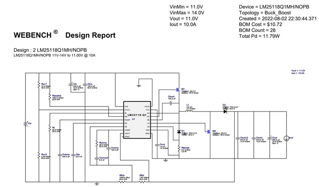
Although parts proposed by 'WEBENCH' could not be used due to parts supply and demand problems, parts with similar specifications were used as much as possible.
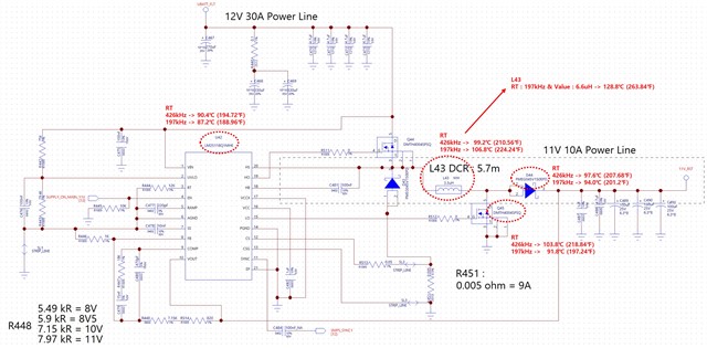
The design specification is 10A with an output of 11V, but the heat of the components exceeds the allowable range even if only 6 amps flow from the actual board. (PCB is 10 layer board)
The figure shown in the actual circuit diagram is the heat measured when 6 amps were spilled for 5 minutes. When two 3.3uH inductors were connected in series (6.6uH), the surrounding parts decreased slightly, but the inductor became 30℃ hotter.
/cfs-file/__key/communityserver-discussions-components-files/196/LM25118Q1_5F00_11V10A.pdf
I don't think lowering the switching frequency is the answer. I need your help. Please tell me how to lower the fever.
Thank you.
