This thread has been locked.

If you have a related question, please click the "Ask a related question" button in the top right corner. The newly created question will be automatically linked to this question.

UCC28019:gate signal abnormal

Other Parts Discussed in Thread: UCC28019

部件號: UCC28019

我正在嘗試使用 UCC28019 設計 PFC(390V,600W)。Vin 介於 85-265 Vac 之間,但輸入電壓為 110V(rms) 和 260V(rms) 時電感電流波形不同。電感電流在 200Vac 以上開始失真。我該如何改善這個問題?或可能的原因
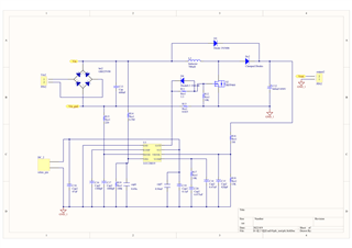

7041.pfc_01.pdf

設計參數

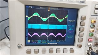
Vin : 110V (rms) 負載: 50%(300w)

CH1:Vin 110V (rms) CH2:VGS CH3:IL (rms) CH4:Iin (rms) 

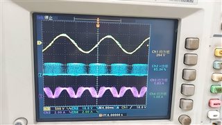
Vin : 260V (rms) 負載: 50%(300w)

CH1:Vin 260V (rms) CH2:VGS CH3:IL (rms) CH4:Iin (rms) 

  • Hi Forger,

    Thank you for sending the schematic and the waveforms.

    I ran the excel calculator and compared with your schematic value for the given system specifications. There were a couple of things which I wanted to bring to your attention and see if it helps the waveform.

    1. The recommended value of sense resistor is around 0.044 ohm from the calculator whereas the value used is only 0.025. The voltage at the ICOMP pin if lower than 0.6V can disable the controller, so might wanted to monitor your ICOMP pin especially at high line voltage and consider increasing the value of sense resistor to see if this helps.

    2. The value of compensation network is not tuned for the voltage loop as per the excel calculator. They require minor modifications. Please find the attached excel for making modifications.UCC28019_calculated.xlsx

    Please let me know your observations after testing.

    Thank you

    Regards,

    Harish