This thread has been locked.

If you have a related question, please click the "Ask a related question" button in the top right corner. The newly created question will be automatically linked to this question.

TPS2492EVM-003: After Tripping the Current Limit, Cycling the UVEN does not release the Fault Latch with a load current.

Part Number: TPS2492EVM-003
Other Parts Discussed in Thread: TPS2492,

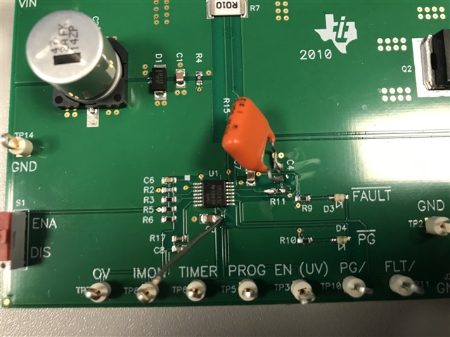
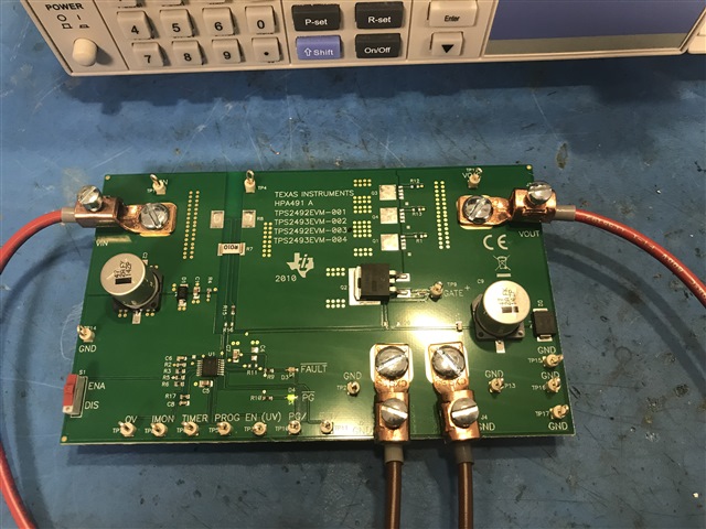
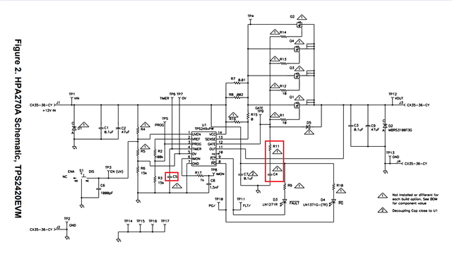
We are developing a design featuring the TPS2492 and have purchased an Evaluation board (TPS2492EVM-003) to characterise the IC while we are developing the design.

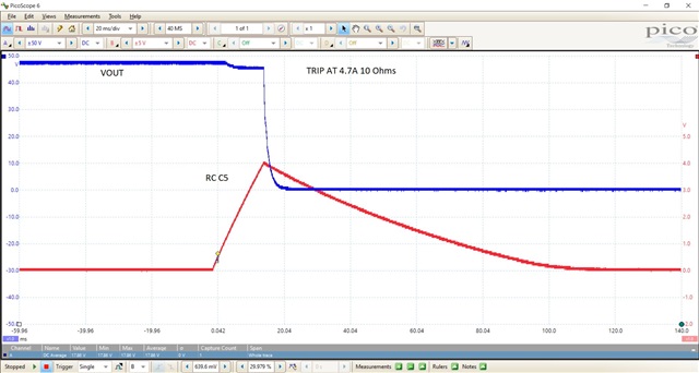
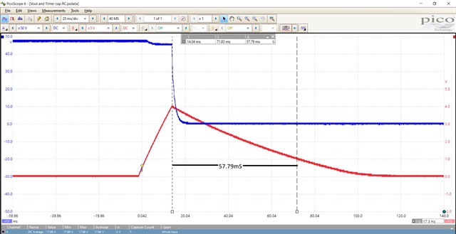
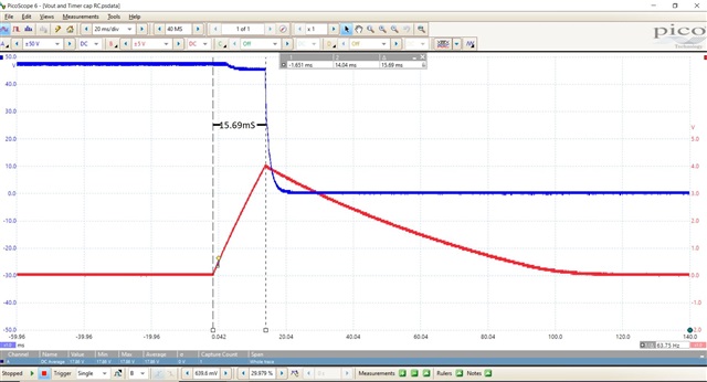
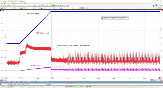
We are seeing some unexpected behaviour after tripping the current limit on the Eval board. After winding down the load current back below the trip point, and cycling the UVEN (via the on-board switch S1), the output does not come back up.

I have attached a video to demonstrate.

We have not adjusted any of the default components or values on the Eval. board.

Is it possible to bring the output back up without the load current being 0A?

Click here to play this video

Many thanks.

  • Hi Peter,

    The load has to be lower than the power limit setting of TPS2492 to make successful startup.

    What is the load type and startup load ? We suggest to enable the load using PGOOD of TPS2492

    Best regards,

    Rakesh 

  • Hi Rakesh,

    Thank you kindly for your response.

    Were you able to see the video I attached of our test setup? That demonstrates our Test Setup.

    We are using the 48V Variant Eval Board 'TPS2492EVM-003' where the configured trip point we understand is 5A.  We found it to be ~4.9A which is adequate for our benchtop tests.

    We started the device Constant Current Load from 1A output, with the PGOOD LED illuminated, and increased it in increments of 100mA to ~5A.  The device trips at 4.9A, correctly de-energises the output and asserts the Fault line, correctly illuminating the corresponding Fault LED.

    We then reduce the Constant Current Load back to 1A, then switching the S1 toggle switch routed to UVEN to 'DIS' (GND) and then back to ENA (NC). After toggling the S1 switch with a Load Current of 1A, the Fault LED and Output Latch were unexpectedly not being released so the output remains de-energised.

    We also tried setting up our Test with a Resistive Load that pulled ~1A on the load.  The output toggles ON and OFF correctly, via switch S1, in that scenario but we then adjusted the output resistance to pull ~4A through the load and again observed that toggling the S1 switch correctly de-energises the output, but then doesn't release the latch to re-energise the output.

    Is there anything in the passive conditioning components that we perhaps need to adjust, or generally should be aware of with our load currents and permissible headrooms, etc?

    We were expecting, for example, that the output should be able to toggle when within the permissible current thresholds (below trip point) and output voltage has not changed.

    Many thanks,

    Peter Seetal

  • Hi Peter,

    The tool is not supporting to view the video. Can you please attach as images.

    Please use resistive load or your end application load for evaluation. Some e-loads behave weird in constant current mode.

    Can you please share Vout, Timer voltage, GATE and current waveforms to check. 

    The maximum load you can startup is Plim/48V. You need to increase the power limit threshold to startup higher loads

    Best Regards,

    Rakesh

  • Hi Rakesh,

    Thank you kindly for your response there.

    I will upload a .mp4 video instead of the .mov after this message. Perhaps that will be more to the liking of the plugin. 

    Thus far we have tested the Evaluation board with the following loads:

    • Electronic Load- Constant Current Sink
    • Electronic Load- Constant Resistance
    • Stepper Motor Module

    There will be several channels in this design, each with its own Hot Swap Controller (being used like an eFuse- There's an ideal diode IC further upstream). The Stepper Motor Module is the most Power Demanding load amongst the several channels and will have its own dedicated Hot Swap Controller IC.

    With the Constant Current Sink load, as mentioned, increasing the load current in increments of 0.1A from 1A to 4.9A (triggering current trip)- after decreasing Load Current to 1A, switching S1 to "DIS", and then switching S1 to "ENA"- the Output Fault Latch did and would not release until we decreased Load Current to 0A.

    With the Constant Resistance Load, we started the device off with 20R (~2.4A Load Current), and decreased the Load Resistance to 9R (triggering current trip)- after switching S1 to "DIS", increasing Load Resistance back to 12R (~4A Load Current), and then switching S1 to "ENA"- the Output Fault Latch did not and would not release. If we increased the Load Resistance to ~20R again it does release the Output Fault Latch and Asserts the PGOOD Output. Waveform images from a Picoscope are attached for 20R and 9R Load showing 'Vout' on Channel 1 and 'Vtimer' on Channel 2.

    With the Stepper Motor Module we intend to use attached, there was a large inrush current initially.  We removed C4 from the Evaluation Board and replaced it with a suitably rated 100nF capacitor (Image Attached). That resolved the inrush current issue and correctly toggles the Output ON and OFF (Latching/ Releasing the Fault Latch correctly). I've attached Vout, Iout, and Pout Waveforms with this Stepper Motor Module on the Hot Swap Controller Load.  We then placed a 4700uF capacitor across the Motor Module which the Manufacturer recommends and were then not able to "Correctly" toggle the Output ON and OFF when moving the S1 Switch from 'ENA' to 'DIS'.  Unfortunately, I don't currently have any waveforms to share with the 4700uF Capacitor across the Load.

    Other than replacing C4 with a 100nF Capacitor, the Evaluation Board has all the default components still fitted.  We have the 48V, 5A Board Variant.

    I'd be interested in hearing your thoughts and recommendations for any configuration changes we may need to make to the Board, or alternatively, any Design Recommendations to drive our Stepper Motor Module load.

    Please find below a link for the Stepper Motor Module we are using.  Also attached are several Waveform photos labeled accordingly.

    https://en.nanotec.com/products/2485-pd4-e601l42-e-65-2 

  • 100nF C4 Capacitor Mod to resolve inrush with Stepper Motor Module Load.

    Default configuration of our board. Electronic DC Load Measurements (Constant Current and Resistance) all made in this state.

    Vout and Vtimer with Electronic DC Load (Constant Resistance)

    Vout and Vtimer with Electronic DC Load (Constant Resistance)- Discharge Duration

    Vout and Vtimer with Electronic DC Load (Constant Resistance)- Charge Duration

    Vout, Iout and Pout with Stepper Motor Module as Load- This was taken with the C4 Mod. in place

  • Thanks Peter.

    What is the PLIM threshold set in the design ? Can you calculate using equations 11 and 12 in the data sheet https://www.ti.com/lit/ds/symlink/tps2492.pdf and let me know.

    As I mentioned, the startup load has to be < Plim/48V for successful startup.

    Best Regards,

    Rakesh

  • Hi Rakesh,

    I've just had a quick play around with equations 9, 11, and 12 in the Datasheet. I'm getting some rather odd numbers out from equation 9 in particular, which firstly I'll need you to sanity-check, and secondly is surprisingly low, if correct.  I couldn't compute equation 12 as I don't know the value for Plim(act).  Rearranging equation 11, I got 0V52 for our 'Vprog'.  Unfortunately, I can't physically measure the actual Voltage on 'Vprog' at the moment. 'Vref' should be 4V I imagine. Using equation 9 I got 19.6W.

    I would appreciate it if you can confirm what 'Plim' you get for our circuit also, please?  Hopefully, it's documented somewhere as it's TI's Design being the default Evaluation Board (48V 5A config.).

    Our evaluation board is in the Default Configuration (Page 9 and 10 of your Eval Board User Manual, link below) with the exception of R11 and C4 now being populated. R11 = 1k and C4 = 100nF currently. Our load is capacitance we kick off with 5000uF.

    https://www.ti.com/lit/ug/sluu425a/sluu425a.pdf?ts=1660815218322 

    The transistor featured on our 48V 5A Evaluation Board is Q2, Datasheet below:

    https://4donline.ihs.com/images/VipMasterIC/IC/INFN/INFN-S-A0010930805/INFN-S-A0012826870-1.pdf?hkey=6D3A4C79FDBF58556ACFDE234799DDF0 

    Realistically we are expecting our Load Current to be ~4A Steady State in a worst-case scenario, 48Vout of course.  The 5A Trip Point is adequate on the Eval Board for confirming the functionality of the device with our Load.

  • Hi Peter,

    we know VREF = 4V

    R4=100k; R5=15k

    Calculate VPROG => 0.52V

    From eq(11) => PLIM= 10 x ILIM * VPROG = 10*5A*0.52V = 26W

    So, the max load you can start is 26W/48V = 0.54A

    Please feel free to use design calculator

    Best Regards,

    Rakesh

  • Hi Rakesh,

    Fantastic, thank you kindly.  Apologies, I missed that trick of rearranging equation 10... Long week! Haha.

    Can I ask also, Rakesh, what is your recommendation for starting up our Stepper Motor Module with Parallel 4700uF loading our circuit there? Obviously, we'll be expecting a generous startup transient inrush event.

    Is it best to choose a suitable Ctimer (C5 in below Circuit Snippet) value or populate the Resistor and Capacitor combo. to the external FET Gate (R11 and C4 below)?

  • Hi Peter,

    I will get back on Monday 

  • Hi Peter,

    Since 4700uF is large, we recommend to use dvdt based startup by using below pnp circuit than RC circuit. The advantage here is the Cdv/dt has local discharge path via Q2 and not into the GATE pin of the hot-swap IC.

    Please use design calculator available at https://www.ti.com/lit/zip/slvc033 to calculate the Cdvdt value. Enter the startup load details from Stepper Motor Module by estimating how much current it draws during startup when powered by bench top power supply.

    Best Regards,

    Rakesh

  • Thank you kindly for your support, Rakesh.

    I'll drive things from this point bearing your recommendation in mind.

    Many thanks.