This thread has been locked.

If you have a related question, please click the "Ask a related question" button in the top right corner. The newly created question will be automatically linked to this question.

TPS61235P: GROUND SYMBOL ON SCHEMATIC

Part Number: TPS61235P

Hi, 

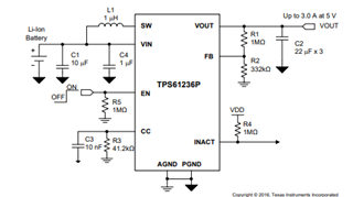
I was wondering why are there different symbols for ground.  Id like to use the CC feature and connect a ~41.4k ohm resistor in parallel with a 10uF capacitor to get an ideal limit of 3A as it would be ideal to get an Voutput of 5.1V/3A for this boost converter. I am confused as to why there is different ground symbols as shown. 

Thanks,

Andy

  • Hi Andy,

    AGND means analog ground while PGND means power ground. We separate them to enhance noise immunity of circuit.

    AGND is used for signal line, for example, EN signal and INACT signal. PGND is used for power line, like VIN and VOUT. In customer's application, you need to connect these two pin with only one line, which is called single-point grounding. This can reduce impact of power line noise on signal line.  You can also take the layout in datasheet or EVM board user guide as reference. 

    Best Regards,

    Nathan