This thread has been locked.

If you have a related question, please click the "Ask a related question" button in the top right corner. The newly created question will be automatically linked to this question.

UCC28633: Malfunction in low power situation

Part Number: UCC28633
Other Parts Discussed in Thread: UCC28634, UCC28631

Dear Sirs.

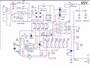
We have designed a flyback conveter using the UCC28633  with a defined output of 65V following the recomendations from corresponding technical notes.

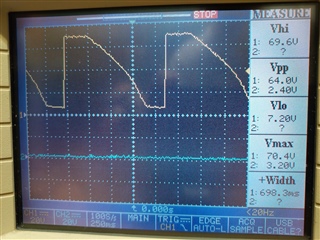
But we are having problems controlling very light loads. By now, our unique solution has been to add a minimal consumption so we can guarantee the voltage output.

However according to datasheet (chapter 8.3.21 ) the component should be able to regulate in this low power situation.

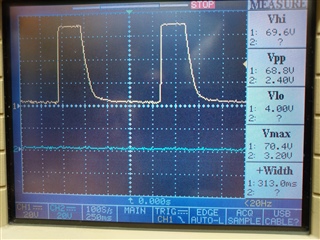
After adding minimal power consumption of 10W it works perfectly, and it avoids the overvoltage alarm at the output.

Anyone could give us some advice for this desing?

Thank you for your help

  • Hello Bernat,

    Thanks for your post and sharing some of your specifications. 
    We’re reviewing this case and will respond within 48 hours. 

    Can you share waveforms/simulations/images demonstrating the behavior you’re describing? 

    Regards,

    Andrew

  • Hello,

    The UCC2863x devices are primary side regulated flyback controllers.  This device controls the duty cycle by modulating the frequency and peak current.  This device controls the frequency down to a minimum of 200 Hz.  To keep these devices in regulation at no load requires a pre-load resistor (Rpre_load).

    Based on your design knowing the maximum freuqency (fmax) and max output power (Pmax) with the following equations to calculated the require Rpre_load to keep the design stable at no load/light load.

    Fmax/(Vout^2/Pmax) = 200 Hz/Rpre_load.

    Rpre_load = 200 Hz*/(Fmax/(Vout^2/Pmax))

    Regards,

  • Hello Mike,

    Pmax is 100W.

    Following the formula with our Fmax we would require a minimal Rpre_load  of 10W.

    That's because our device is not working at 200Hz, it works in a higher frequency.

    We don't know how to reduce its frequency.

    What it does for a Rpre_load  smaller of 10W is to trigger an overload alarm and stop the Vout.

    How we can reduce its working frequency point until 200Hz?

  • Hello,

    10W sounds like a lot.  For a 5 to 10 W design it generally takes 1 or 2 mA of load to keep the design in regulation.

    200 Hz should be the no load frequency.

    The data sheet give slightly different equation.  You can try using it to set your pre-load resistor.  Hopefully it yields a better result. 

    Regards,

  • We have verified that if our load is less than 10W the output voltage raises and the chip triggers overvoltage alarm and stops the output  and restarts the output after 100ms in infinite loops.

    We don't know why the chip is not reducing its frequency so we can work with preload charges smaller than 10W

  • Hello,

    If you have filtering on the VS pin it could cause the design to misbehave and could trigger an OVP.  Please do not use more than 3.3 pF of capacitance on the VS pin.

    Do you have a schematic and waveforms of CS, Aux, VDD and Vout when the device is hitting OVP that you can share?

    The following link will bring you to an application note that describes the most common issues with primary fault sensing and how to remove them.  You may find this information useful as well in debugging your issue as well.

    https://www.ti.com/lit/an/sluaac5/sluaac5.pdf

    Regards,

  • Hi Mike,

    As you requested here you can see the schema from the flyback attached.
    We have already applied following changes to attached schema but without success=

    - Current sense measurement is now performed by 4 resistors of 1ohm
    - Transformer has a inner inductance in primary side of 310uH,

    Appart from this we have done several tests with different loads. You can see attached our results, measuring the output:

    Output without any load (unestable)

    Output with load of  540 ohm (still unestable, due not enough consumption)

    Output with load of  390 ohm (minimal load that we need to get a proper output in the +65V line)

  • Hello,

    I reviewed the schematic.  I would replace the TVS clamp with and RCD clamp.  I would also add place holders for an RC snubber across the output rectifier.

    These devices do require a pre-load resistor to stop the design from hitting OVP.  I would also add a resistor to load the output with 1 to 2 mA.

    The most common issue with primary side regulated flyback converters is a noisy aux winding triggering over voltage protection (OVP) or input under voltage.  A noisy CS signal can trigger  over current protection OCP.  The following link will bring you to an application note that discusses these issues and how to resolve them. 

    https://www.ti.com/lit/an/sluaac5/sluaac5.pdf

    After reading the application note.  You will need to probe VDD, the aux winding voltage, CS and Vout to figure out why the design is shutting down.  From there you can figure out why your converter is shutting down.  Most likely you will be able to resolve this issue with and RC snubber circuit and/or RC filtering.  

    Regards,

  • Hi Mike,

    We have reviewed the signal in the bias of the transformer but we don't see a ringing that could cause the problem.

    At 750ns (page 5 of document) the signal is clear

    In the case of 540 ohms of load the output of flyback is stopping intermittently.

    load 350 ohm flyback working

    load 540ohms flyback not working properly

  • Hi Mike,

    We found the solution!

    We previously used the UCC28634 and then we changed for the UCC28633 because the UCC28634  has a overvoltage voltage detection in Vdd too much sensible for our circuit.

    But we didn't take on account to change the start-up schema, so it is activated from two diodes previous to recitifer component as it is explained in corresponding datasheet.

    We supose that if we replace this component for the UCC28631, we will not have to change the start-up circuit that we originally had from UCC28634 board

    Thank you very much for your patiente