This thread has been locked.

If you have a related question, please click the "Ask a related question" button in the top right corner. The newly created question will be automatically linked to this question.

UCC2800-EP: Synchronization of PWM controllers using SYNC pulse

Part Number: UCC2800-EP
Other Parts Discussed in Thread: UCC2800

Hi,

This is in reference to PWM Controller IC: UCC2800-EP

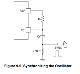
There is a section in the datasheet of the IC where the method is shown to synchronize the PWM controllers (Section 9.3.6). However, it is mentioned that the oscillator of IC is programmed to run at frequency 20% lower than that of synchronizing frequency. In this case if my PWM switching frequency is 120 kHz of FLYBACK, than the external sync pulse should be of 144 kHz? And a positive pulse description is to be applied at 50 Ohm resistor. 

But still the picture is not clear, how exactly to design that external sync circuit and what would be the signal characteristics? It's magnitude, duration, or any other considerations regarding its source of generation.

Thanks

Ravi

  • Do you refer to the D/S from ti.com?

    https://www.ti.com/lit/ds/symlink/ucc2802-ep.pdf?ts=1663266031157&ref_url=https%253A%252F%252Fwww.google.com%252F

    But I don't find section 9.3.6. Can you make a screen shot of the picture you mention?

  • Hi,

    Sorry to mention you, but the detail description of all the functioning is provided in the datasheet of UCC2800, below is the link.

    https://www.ti.com/lit/ds/symlink/ucc2800.pdf?ts=1663234826683&ref_url=https%253A%252F%252Fwww.ti.com%252Fproduct%252FUCC2800

    Thanks & Regards

    Ravi

  • Hi, 

    The sync input needs 1V and minimum 100ns pulse width amplitude.

    There are two ways to implement SYNC:

    1)


    2). Directly apply the sync signal to RC pin without RT and CT.  There is 130 ohm internally and make sure the input signal has enough drive capability.

    Regards,

  • Hi,

    Thanks for the update. However, I have few more clarifications to ask for.

    1. Is 1 V and 100ns of pulse width is necessary or there is any other consideration. Besides, I have fixed the IC to switch at 120 kHz and want to sync 6 such controllers. Does this 1V and 100 ns pulse train is enough? And if yes, then when exactly to provide the pulse train, during start-up or continuous.

    2. Is there any specific current requirement for driving this sync circuit or it can be energized from microcontroller output pin?

    3. Any consideration to be taken care of such as noise or other disturbances, in order to make this circuit work perfectly?

    Are there any application notes pertaining to this sync pulse set-up circuit. If yes, kindly provide the link.

    Thanks 

  • Hi, 

    The consideration is source capability. With 50 ohm connected to ground, The source needs  to provide 20 mA current. Normally, MCU can't provide such large current, and you need buffer.

    The pulse width need be 100ns or wider. and it need a clear waveform to avoid a fake trigger.

    Regards,

  • I understand Method 2 (direct application of sync signal pulse train to RC pin). Thanks for explaining that.

    I have the following questions regarding Method 1:

    1)  I interpret that a single pulse (≥1V, ≥100ns) is required to be applied to synchronize the multiple UCC2800 devices. Is it true that only a single pulse is necessary on startup? Or is a pulse train needed at the desired synch frequency?

    2)  The data sheet states "The IC is programmed to free run at a frequency about 20% lower than that of the synchronizing frequency." Does this mean the RT and CT values should be designed for 20% below the target frequency? If so, why?

    3)  What advantages does Method 1 offer over the direct sync signal of Method 2?

    Thanks,

    Dan

  • Hello,

    1). Sync signal needs pulse trains to make fixed output frequency. A single pulse just syncs once, and then PWM goes back to RC free run frequency;

    2) Yes. When RC free run frequency is lower, sync signals can chop the period earlier and then they can sync together;

    3). Method 1 is better. When external sync signal is gone, the converter still can operate. In method 2, if external sync is gone, the converter stops to operate because there is no frequency programmed.