Other Parts Discussed in Thread: UC3843, UCC28951, UCC28950, LM5036, UCC3895, UCC2895, LM5045
Hello.
My name is Patty Karigi
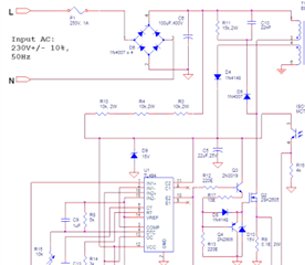
I am designing a push pull converter (CCM) with an output of 12V 30A (360W) using the tl494 ic from an input of 36V to 86V. Here are the questions I have about the design:
1) I am using secondary side regulation and I wanted to use two tl494 ics, one for driving the primary side switching mosfets and the other for driving two secondary side rectification mosfets in place of diodes to lower the losses. In the tl494 data sheet, I have seen that one can sync two tl494 ics. My question is, can this work practically in my case where one ic controls the primary side mosfets and the other the secondary side mosfets?. From a simulation I did on LTspice, I found that I can use the collector of the ic that drives the secondary mosfets to provide an overlap on each switching transition. Is this overlap enough to ensure optimal performance of my power supply?
2) If I can use two ics as explained above, How do I terminate the other terminals of the slave ic i.e the error amplifiers,feedback pin, and the output control pin? This is not explained in the datasheet.
3) In the case of secondary side regulation, How do I provide vcc supply to the ics without using an auxiliary power supply?
4) From a simulation I did on LTspice, I found that the emitter provides an output voltage close to the vcc supply voltage. My question is, isn't the emitter a voltage follower which follows the 5v reference voltage or is the case different for tl494 such that the emitter voltage is almost equal to the vcc voltage?
5) From the TL494 datasheet(Designing Switching Voltage Regulators With the TL494 (Rev. E)), it is stated that there is usually a synchronization start up problem when syncing to a system clock. Does this apply to the master/slave sync configuration of multiple tl494 ics? If yes, how do I deal with it?
6) From the datasheet(Designing Switching Voltage Regulators With the TL494 (Rev. E)) pg 19, one can configure the Ic to use peak current limiting. Can I use this configuration to track the input current using a current sense transformer? If yes, does this convert the ic to a current mode controller whereby I have to treat the control loop as a current mode control loop and also use slope compensation?
7) From an article I read, I found out that push pull converters usually use current mode controllers and if one has to use use a voltage mode controller, one has to take into consideration the flux imbalance problem (https://nanopdf.com/download/voltage-mode-push-pull-converters-deserve-a-second-look_pdf). They proposed that if one uses a voltage mode controller, one can use a gapped transformer to increase the current handling capabilities of the transformer. My question is, is this good practice? If yes, how do I go about sizing the inductance of the transformer whereby form my calculations, I am getting a minimum magnetizing inductance of 300uH while using an output inductance of 30uH with a switching frequency of 30KHz and a primary to secondary turns ratio of 2.
If I use a gapped transformer, then increase the number of turns to get a higher inductance, will that cancel out the advantage of using a gapped transformer in the first place? or should I just maintain the same number of turns that I was to use with an ungapped transformer core which will result in a decreased inductance?
8) If I use peak current limiting configuration, can I avoid flux imbalance of the transformer?
9) .From my calculations, I am getting a peak current of 17A on each primary side switch and an rms current of 9.35A on each primary side switch. I wanted to reduce the strain on the input capacitors by using an input inductor, pls help me understand the design of the input LC filter for a push pull/ other buck derived topologies and how it might affect the input peak current especially if I am to use peak current limiting configuration. Will it affect the peak current sensed at the input? which in my case is 17A.
Kindly assist me. I will greatly appreciate your help and I also thank you for the help you have offered me in the past which has greatly assisted me in understanding power supply design.
Thank you.