This thread has been locked.
If you have a related question, please click the "Ask a related question" button in the top right corner. The newly created question will be automatically linked to this question.
Messrs TI,
I am testing a custom board with two TPS22910A devices that share the same output; this is because each of them manages two different power source for the board (USB 5V_EXT & Battery VBAT).
I attach here the schematic for your reference:
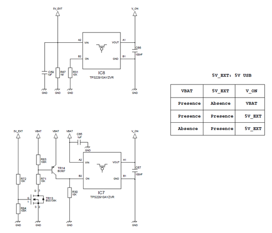
My concern is regarding the output shared by the two TPS22910A because we are facing an issue when the board is powered from battery: it seems that IC7 doesn't output the battery voltage (VBAT) on V_ON net.
Do you have any suggestions for optimizing this design?
Best Regards
Hello Luigi,
Have you looked into using a priority power multiplexing device such as TPS2116? That device ensures break-before-make logic and has fast switch over to prevent the output voltage from falling significantly. I believe it would be a better fit here.
In terms of TPS22910A- are you able to probe the ON pin voltage to see if the VIH voltage requirement is being met? Also, if both devices are ON you still may see some reverse current due to the required voltage drop from Vout to VIN to enable RCB (~54mV) just FYI.
Regards,
Kalin Burnside
Very interesting the TPS2116 for this application! Is feasible to connect it to a battery charger IC too?
Do you think that having both the TPS22910A in ON state, could be cause some failure of the switches (current and/or voltage)?
IC8 can be in ON state, but without a voltage applied to its input, but with a voltage in its output given by IC7...could be an issue this situation?
Regards
Hello Luigi,
Yes you can. Using it here would prevent concerns for reverse current between rails since only one rail would be passed to the output at any one time. You would have to confirm the specifications of the device meet your system.
No, the failure would not occur in the load switches but somewhere along the path upstream in that situation. When the device does not switch ON it's usually due to either an invalid input to ON or the ON pin experienced a transient outside its ABS values. Were you able to switch out the device to see if a new one works (even momentarily) or probe the ON pin with VIN and VOUT as well?
There will be some reverse current in the event both devices are ON and one is at a slightly lower potential. As indicated previously the device would need to see 54mV drop from Vout to VIN before engaging RCB which could result in reverse current until that point. This could pose a problem for your upstream ICs.
Regards,
Kalin Burnside