Hi
Could you help check the TPS23751 schematic and any need to adjust
This thread has been locked.
If you have a related question, please click the "Ask a related question" button in the top right corner. The newly created question will be automatically linked to this question.
Hi GARETH OU,
Thanks for reaching out to us!
Sure, we will check your schematic and send feedback to you by this Wednesday.
Best regards,
Diang
Hi GARETH OU,
Please find the comments from us. We mainly checked the 04. POE PD, and for 03 & 05 we only have a general glance. Please let us know if you have any further questions.
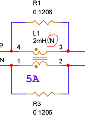
1.Just for confirmation: does “/N” mean unpopulated?
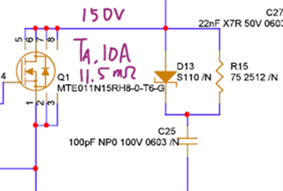
2.The current rating of the primary side NMOS could be too high for 25.5-W output power. The estimated rms current is 1.1 A based on our tool. It is recommended to use 5-A Ta or lower current rated device for less switching losses.
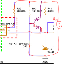
3.I would assume R43 and C50 are for Vout error amplifier delay. Two diodes need be added to make the delay time activated (lower diode for startup delay, upper diode for C50 discharging at turn off). You could refer to TPS23751EVM.
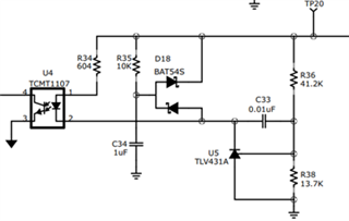
4. The CTL pin is connected in the feedback loop normally. Seems I did not find the connection point for it.

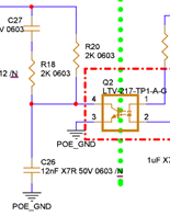
5.The capacitance of VC could be further increased. Considering the 10-uF 0603 ceramic capacitance dc bias, the equivalent capacitance of C21&C52 could be assumed as 6 uF, and the startup sourcing current is 1.1 mA to 2.1 mA. With 8.9-V startup threshold voltage, the startup delay is about 25.4 ms to 48.5 ms. While the shorter bond 25.4 ms could be too fast comparing to the inrush delay. So, the capacitance of VC could be doubled.


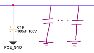
6. On the input side of power converter, it is better to add some ceramic capacitors (~1-uF). C19 could be a good dc-link capacitor for stabilize the input voltage for dc portion. Some additional capacitors (normally ceramic capacitors with small ESL and ESR) are used as decoupling capacitors too. The locations of decoupling capacitors are important in the layout too.
Best regards,
Diang
Hi Diang
1. /N is not uploading
2. How about BSC093N15NS5 ? or have other suggestions
3.Schematic has been modified as follows
Hi GARETH OU,
Thanks for your updates!
BSC093N15NS5 has even higher output capacitance (604 pF) than MTE011N15RH8-0-T6-G (276 pF). SI4848DY-T1-E3 or FDMS86250 which have ~100 pF Coss could be considered at your power rating.
By the way for "4375.TPS23751_20201214.pdf" you attached, do you also need the schematic review or it has been a product?
Best regards,
Diang
Hi Diang
1.How about this SPR60N15SV-C
SPR60N15SV-C(PR-8PP)N-Ch(R,C,vB) (secosgmbh.com)
2.4375 is a wrong link please ignore
3. Schematic has been modified as follows
4.Could you help confirm placement has comments
Thanks
Hi GARETH,
Thanks for your updates!
SPR60N15SV-C looks good to me.
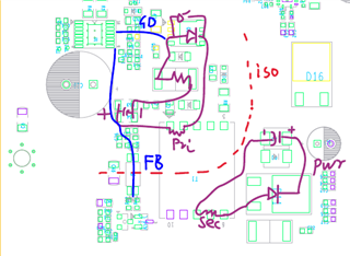
For the placement of PoE part, I could see the power loop of input side (PRI purple line) for flyback converter could be further shorten if some components could be placed on the bottom layer. Secondly, try to make the feedback line (FB blue line) not crossing the power loop for the consideration of noise.
I also attached a check list for PD layout. Hope it could help!
Best regards,
Diang
Hi Diang
Please help review attached BRD
AW5601_PB_V01_2022-1109-1838_TOP.pdfAW5601_PB_V01_2022-1109-1838_L3 VCC.pdfAW5601_PB_V01_2022-1109-1838_L2 GND.pdfAW5601_PB_V01_2022-1109-1838_BOT.pdf
Hi GARETH,
Thanks for your updates.
The layer review sometimes is hard to be accurate and efficient for us since it is hard to know every polygon/trace's net.
Please use the attached layout review instruction and hope it could help for your review.
8611.PoE Layout Check LIst.xlsx
Updated on Jan/17/2023: It has been a relatively long period that we have not received your reply. I will close this thread for now. Please open a new thread if you have further questions.
Best regards,
Diang