This thread has been locked.

If you have a related question, please click the "Ask a related question" button in the top right corner. The newly created question will be automatically linked to this question.

BQ25720: Component suggestion to replace inductor and MOSFET

Part Number: BQ25720
Other Parts Discussed in Thread: CSD17578Q3A, CSD18511Q5A

Hi,

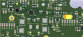
I have designed a custom charger based on bq25720. I need help regarding selection of inductor and 4 switching N-channel MOSFET (Q1, Q2,Q3,Q4).

I have used BMRA000606302R2MA1 in place of BMRHDY1010302R2MA1 ( as suggested in bq25720 EVM board).

and SIRA84BDP-T1-GE3 as 4 switching MOSFET in place of CSD17578Q3A (as suggested in bq25720 EVM board).

Though I have used these components after comparing the spec with the one used in EVM board but I guess these selection might not be correct

as while charging at 4 amp temperature of Mosfet Q1 & Q2, Inductor and nearby PCB area is increasing upto 60-65 degree celsius.

Though charging is happening but the these components are becoming very hot. If I charge with the bq25720 based EVM board temperature rises near to 45 degree celsius only and that too of inductor only.

Note: My PCB board is of 4 layer and I have tried to follow the guidelines as per EVM board. 

I am using 24V, 2A power adapter.

I have attached the image of arrangement of MOSFET and Inductor in the PCB. 

  • Hi, Amit,

    The layout is very good by following our EVM layout. Regarding the component replacement, I would suggest replacing the components with similar spec. For example, the EVM inductor is 2.2uH, 9-mohm, however, the replacement inductor is 2.2uH, 20-mohm. It is going to have high temperature due to increased conduction loss. 

    Same rule applies to the FET replacement. EVM FET is about 8-9 mohm, 10nC FET. If you use 1.35mohm, 38nC FET, it won't help much. The switching loss and driver loss may out weight the conduction loss. 

    The EVM has been optimized for efficiency. Suggest using the same components or similar ones. 

    Regards,

    Tiger

  • Hi Tiger,

    For inductor then I guess I can use either BMRF001010402R2MD1 or SRP1038A-2R2M (both are having 7mOhms ).

    But in case of MOSFET as I can see from the datasheet of SIRA84BDP-T1-GE3, RdsOn is 5.2mOHm-7.1mOhm and gate charge is b/w 10.9nC-16nC.

    So, this should be fine as it is closer to the one used in EVM. I have attcahed the snap from datasheet for reference.

    Please let me know if I am looking at correct parameter or not.

  • Rdson and gate charge are two important parameters for the FET replacement. Suggest using the same components or similar ones.

  • Yes, I understood that part. That's why I want to get clarification specially about the MOSFET ( SIRA84BDP-T1-GE3 ) which I am using currently. In the very first reply you had mentioned that "If you use 1.35mohm, 38nC FET, it won't help much"  but as I can look into the datasheet of SIRA84BDP-T1-GE3, I can see that Rdson is in range of 5.2mOhm to 7.1mOhm and gate charge is in b/w 10.9nC - 16nC but from where did you refer to 38nC I am not getting.

    Since MosFET used in the EVM is out of stock in most places, I need to find the replacement.

  • HI, Amit,

    Not sure why I checked this FET. 1.35mohm, 38nC FET is SiRA60DP.

    SIRA84BDP is better than SiRA60DP, which is closer to the TI FET. 

    Still TI FET CSD17578Q3A has better performance than competitor's part. Another FET we used is CSD18511Q5A, 5mm X 6mm package. 

    Regards,

    Tiger

  • But Both of the Ti's IC are out of stock and infact CSD18511Q5A has higher gate charge of 31nC. If I change only inductor and let the MosFET be same as SIRA84BDP then will it help? I mean out of both inductor and MOSFET which is more responsible for heat?

    My maximum charge current is going to be 4A only.

  • Hi, Amit,

    I wish I have a loss calculation tool to help you. My suggestion is to try them in the circuit and the test data will speak for themselve. 

    Regards,

    Tiger

  • Hi Tiger,

    I just have one more doubt related to the MOSFETs. As I mentioned earlier gate charge of both the mosfet CSD17578Q and SIRA84BDP is almost similar and RdsOn is infact lesser in case of SIRA84BDp but still there is significant heating in case of SIRA84BDP. So, apart from RdsON and gate charge could there be any other parameter which is responsible for that?  Like turn on delay time, rise time, turn off delay time, as in case of SIRA84BDP it is quite higher as compared to CSD17578Q.

    I have attached the snap from datasheet of both the component.

  • Hi, Amit,

    Definitely, the switch time will have an impact on the switching loss and efficiency. This correlates to the worse efficiency from the competition. 

    Regards,

    Tiger