Hey there!
I am having trouble with my BQ25570 based PCB.
The charging of my super capacitor works fine, the digital part of the circuit after the BQ25570 works fine as well on it's own, but it never gets powered by the buck converter.
I have tied VBAT_OK to VOUT_EN to enable the buck converter, when the Voltage of the supercap is high enough.
But no matter the voltage of the supercap, the buck converter never outputs 1.8V, but always around 500mV.
Furthermore I feel like the Supercap Voltage is decreasing really fast, until it reaches my VBAT_UV.
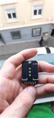
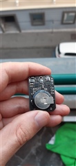
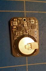
I append the schematic and also pictures of my soldering job. (Also under a microscope if needed)
I hope you can help.
With kind regards,
Felix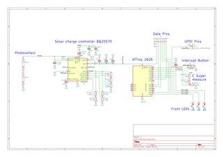

-
Ask a related question
What is a related question?A related question is a question created from another question. When the related question is created, it will be automatically linked to the original question.