This thread has been locked.

If you have a related question, please click the "Ask a related question" button in the top right corner. The newly created question will be automatically linked to this question.

TPS54561: UVLO resistance configuration

Part Number: TPS54561

Hi TI

For the Figure 8-1. 5-V Output TPS54561 Design Example of TPS54561 datasheet Rev.G, 

Start input voltage (rising VIN) = 6.5V

Stop input voltage (falling VIN) = 5V

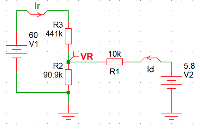
Then, we get Ruvlo1=441k and Ruvlo2=90.9k by equation 45 and 46. so R1=442k and R2=90.9k.

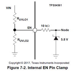
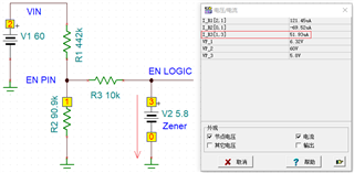
But, we will also get that the en/uvlo pin voltage is 60*90.9/(442+90.9)=10.23V, this 10.23V is over the en/uvlo pin internal 5.8-V zener diode voltage. I think this is not good operating condition.

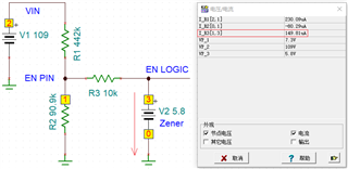
If the input voltage is 34V, and we will get the en/uvlo pin voltage is 34*90.9/(442+90.9)=5.799 which is less than 5.8-V zener diode voltage.

Figure 8-1. 5-V Output TPS54561 Design Example is designed to support input voltage from 7.0V to 60V, But 35V to 60V are not good operating condition.

How we can do with this contradiction?

Thanks,

Kingson

  • Hi Kingson, 

    The method you used to find the voltage at the EN/UVLO pin is incorrect because the actual topology does not assume the voltage divider topology. Instead, the topology is shown in the image below. We can simplify the Zener diode to be V2 at a constant voltage of 5.8V. Zener diodes are designed to hold a constant reverse bias, sinking current up to a specific point where the voltage barrier will break down. According to the TPS54561 datasheet, the Zener diode supporting the EN/UVLO pin can sink a max current of 150uA. 

    Therefore, by system of equations, at our max VIN of 60V the current through the Zener diode (Id) will only be around 52.1uA and thus under the Zener max current breakdown threshold. The voltage at the EN/UVLO pin (VR) will be around 6.32V.

    System of equations:

    441K*(Ir)+90.9K*(Ir+Id)=V1

    10K*(Id)+90.9K*(Ir+Id)=5.8

    For V1=VIN=60V, Id=-52.1uA, and Ir=121.7uA.

    VIN would have to be greater than 109V for the Zener diode to reach the 150uA current sink limit, which is already beyond our max VIN.

    Regards,

    Henry

  • Hi Henry

    You are great.

    I think, there is a internal series 10k resistor at EN/UVLO pin, right ?

    And, Usually, the EN/UVLO pin will have a series resistor ?

  • Hi Kingson,

    Thanks, happy to help.

    See Figure 7.2 below for the internal 10k resistor and diode clamp.

    Regards,

    Henry

  • Hi Henry

    Got it. R1=442k and R2=90.9k are safe enough for the max vin=60V.

    This helps me a lot. Thanks.