This thread has been locked.

If you have a related question, please click the "Ask a related question" button in the top right corner. The newly created question will be automatically linked to this question.

UCC28781: AC-DC Converter with power factor correction

Part Number: UCC28781
Other Parts Discussed in Thread: UCC28600, UCC28056, UCC28050, UCC28051, PMP9730, POWERSTAGE-DESIGNER, UCC256404, UCC256403, UCC38050, UCC38051, UCC28740
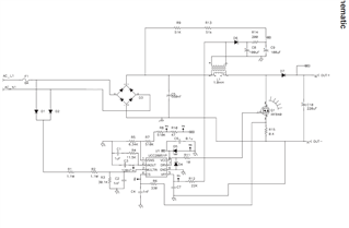
  1. I used WEBENCH but i want probe some points on schematic (add probe in specific point) . how do I do that?


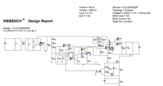
  1. Is there is another IC part with power factor correction? My requirements AC to DC converter with power factor correction AC input 85V -265V Frequency 60Hz output 31DC @ 7A High efficiency.


        another part # UCC28600

       Regards

      Sam

https://webench.ti.com/power-designer/switching-regulator/export/5?noparams=0

  • Hello Sam, 

    Thank you for your interest in TI products. 

    For your question #1:  WEBENCH is calculation program that determines component values based on common circuit topologies and arrangements to achieve the specified output parameters from the input parameters.  It calculates node voltages and net currents based on the network equations and specified conditions. It is not a simulation program such as Simplis or PSpice, and there is no way to place probes into the design. 

    For your question #2: Can you please clarify what you are asking for?  TI has many PFC controllers suitable for a ~220W load.  However, the WEBENCH design report shows a flyback design using UCC28600.  If you looking for a PFC controller for a PFC stage ahead of the flyback stage, the UCC28056 would be most suitable for this power level (although there are other choices, too.  If you are looking for a single-stage-PFC design to go from AC to isolated, regulated DC in one stage, then the UCC28050 or UCC28051 may be used for that.  This reference design gives an indication how single-stage PFC can be achieved, even though it is for only 36W: https://www.ti.com/tool/PMP9730.  The principles of design are the same for higher power.

    Regards,
    Ulrich

  • Hi Ulrich

    Thanks for the email

    a. is there single  part with power factor correction to use with AC to DC converter or   I have to do two stage design?

    b  my requirement is  AC input 85VAC-265VAC Frequency 60Hz output 31DC @ 7A High efficiency.

    c. Please send me refence design information and the WEBENCH design 

    d. I tried WEBENCH® Designer UCC28050 it does not allow me to add parameters?

     e. Please send me the information regarding UCC28056 ,UCC28050 UCC28051 WEBENCH design 

      Regards

      Sam

  • Hello Sam, 

    My replies for: 

    a & b) You do not have to do a two-stage design.  For a single-stage design, I recommend to use the UCC28051 PFC controller, as I mentioned earlier.  It can handle your output power level. 

    c & d) I mentioned the PMP9730 reference design above.  Although your power level is much higher, the design approach should be the same.  Unfortunately, the WEBENCH program for PFC is targeted only for non-isolated boost-PFC designs, and is not capable of generating a single-stage flyback-PFC design.

    e)  Information on those three parts can be found by clicking on the hot-links at the top of this E2E thread, under the thread title, at the line "Other Parts Discussed in Thread:"   As I mentioned, WEBENCH will not be able to generate a single-stage flyback-PFC design for any of these parts. 

    I'll try to find a design guide for you, and if I find one I'll post it in a follow-on reply to this thread.

    Regards,
    Ulrich

  • Hi Ulrich

    Thanks for the email

    a. I have calculated output voltage  UCC28051 PFC controller to 31V using your ref design 

         I have set R10=30 Ohms, R8=30 Ohms R7= 70K R5=6.34V.

        V sense=2.5V @ output 31VDC

    b. I used data sheet Page 14 for Current  Section 8.2.2.6 Sense Resistor Selection

    c. I need help with how set the current output current to 7A. Total wattage is 7AX31V=207W

    d. Do you have a WEBENCH design for UCC28051 PFC controller

    Regards

    Sam

  • Hello Sam, 

    I am confused by your numbers.  
    The reference design that I mentioned is PMP9730.  The resistor reference designators R10, R8, R7, and R5 that you mention in (a) do not correspond to resistors that would set an output voltage.  For R5, you have assigned a voltage to a resistance.  None of these values make sense for the PMP9730 schematic (TIDRGP1.pdf), nor do they make sense for the Typical Application diagram (Figure 19) in the datasheet. 

    Section 8.2.2.6 for Sense Resistor Selection is on page 19 of the latest UCC28050 datasheet, not on page 14. 
    For a flyback design with regulated output voltage, the output current will automatically be set at 7A when the primary side is designed for 7AX31V=217W with some allowance for conversion losses. 

    As I mentioned before, WEBENCH is not capable of generating a flyback-based single-stage PFC design. 

    I think, for your application, it will be more straight forward and successful for you to use the 2-stage approach with a traditional boost-PFC followed by an LLC DC/DC stage (to keep the peak currents lower).  There are many design guides and application notes available for each of these stages in the technical literature associated with the respective controllers of each stage.  WEBENCH works for each of them individually.  

    I suggest using UCC28050 for the PFC stage and UCC286404 for the LLC stage.  
    To explore other topology options for your 217W application, try using the Powerstage-Designer tool which can be downloaded here: https://www.ti.com/tool/POWERSTAGE-DESIGNER .  The Technical documentation under the download button can also help you optimize your selection. 

    Regards,
    Ulrich 

  • Hi Ulrich

    Thanks for the email

    We have miscommunication I am not looking at the PMP9730

    I am looking at UCC28051 ref design below

    100-W Universal Line Input PFC Boost Converter
    Using the UCC28051 

    Please look at the user guide (sluu152a) schematic all the ref resistor designators are there

    Page number 5 has the schematic

    Regards

    Sam

  • Hi Ulrich

    I can not find  data sheet UCC286404?

    There is part # UCC25640x have a data sheet

    Please send me the data sheet for UCC286404

    Regards

    Sam

  • Hello Sam, 

    I apologize for mistyping the LLC part number.  I meant UCC256404, whose datasheet is here: https://www.ti.com/lit/gpn/ucc256403 .
    (Even though the link address shows UCC256403, the -404 is also specified within that datasheet, along with several other variations.)

    Thank you for clarifying where your resistor designators came from.  That design is an EVM (EValuation Module) for a 100-W non-isolated boost PFC.
    Because the output of this EVM is not isolated from the high-voltage input, there is a direct path from the rectified line voltage through the boost inductor and output diode to the output capacitor.  Therefore, it is not possible for the output voltage of this PFC to be less than the peak of the input voltage.  For 265Vrms input, this is 375Vpk, therefore a non-isolated boost PFC is normally regulated to about 390Vdc (generally 15~20V higher than the highest input peak).   
    Changing the values of R7, R8, R10 will not result in an output voltage of 31Vdc.  But the controller will be damaged if VO_SNS (pin1) exceeds 5V.  

    As I mentioned earlier, I suggest to use the UCC28051 controller to regulate a PFC stage to 390V and use UCC256404 controller for an LLC output stage to regulate the 390V bus to 31Vdc at high efficiency.  The LLC transformer will provide the isolation between the high-voltage input and the low-voltage output. WEBENCH and other design tools are available for each of these devices to design each stage separately.  

    Regards,
    Ulrich

  • Hi Ulrich

    I reviewed  the both UCC28051 and UCC256404

    Is there another single chip solution?

    What is LLC?

    Please send me the link to WEBENCH and other design tools 

    Regards

    Sam

  • Hello Sam, 

    The link to WEBENCH for UCC28050/51 is: UCC28050 data sheet, product information and support | TI.com .
    The WEBENCH screen is found by scrolling down to the bottom of the "Design & development" section (about 1/3 of the way down the webpage). 

    The link to WEBENCH for UCC256403 is: UCC256403 data sheet, product information and support | TI.com .
    The WEBENCH screen is found by scrolling down to the bottom of the "Design & development" section (about 1/3 of the way down the webpage). 

    You can fill in the input and output requirements for each stage to get the respective designs started. 

    LLC is a resonant conversion topology involving two inductances and one capacitance, commonly implemented with a half-bridge configuration.
    The "L's" comprise the transformer magnetizing and leakage inductances and the "C" is a capacitor (or split capacitors) in series with the leakage inductance. 
    The basics of the LLC topology can be studied here: https://training.ti.com/basics-resonant-converter-topologies-llc-series .  Many additional training files and videos are at this site: TI training search results | TI.com .  I suggest to sort by date (earliest first) and scroll down to Oct 2017 where the relevant LLC-related  files begin.  (You may need to create a TI account to access this training.)

    Note, you can also enter "PFC" in the search box at the top to find training material on power factor correction.  

    Regards,
    Ulrich

  • Hi Ulrich

    Thanks for the information

    1. I looked at  Mathcad Calculation Tool for UCC38050 Transition Mode PFC

    2. Can I use with UCC28050 ?

    3. The formulas are different compare to UCC38050?

    4. Please send me Mathcad calculation link to UCC28050 

    Regards

    Sam

  • Hello Sam, 

    The MAthCad tool will work exactly the same for either UCC28050 or UCC38050.  

    The two parts are functionally equivalent, except the -28050 specifications are guaranteed for operating ambient temperatures from -40C to +105C, while the -38050 specs are guaranteed only from 0C to 70C.  

    One is an industrial grade part and the other is a commercial grade part.  Design calculations are identical for each. 

    Regards,
    Ulrich

  • Hi Ulrich

    1. If you look at the ref design from UCC38050 (L1)., UCC28050 (L2) are different

    2. UCC38050 (L1) data sheet page 18 Inductor formula is different than  UCC38050 (L1?

    3. Do i have to change the formula?

    UCC28050 (L2

    UCC38050 (L1)

    Please advice

    Regards

    Sam


  • Hello Sam, 

    These two equations are the same. 

    The top equation, which you label as (L2), is found in the UCC28050 datasheet.  This datasheet is common for UCC28050, UCC28051, UCC38050, and UCC38051.  All these part numbers use the same single equation for calculating L.  

    The bottom equation, which you label as (L1), is from the MathCad file and is the same as the top equation from the datasheet. 
    One minor difference is that (L1) uses the variable "Vinmin" in place of "VAC(min)" as the name for the minimum input rms voltage. 
    Another minor difference is that (L1) uses "Pout/η" in place of "Pin" as the factor for the input power. 
    The third minor difference is that the order of terms in the numerator of (L1) is reversed from the order in (L2). 

    If you replace each variable term with its actual numerical value, each equation will result in the same inductance.  

    Regards,

    Ulrich

  • Hi Urich

    Below are Design variables there is PIN?

    How do I calculate Pin= maximum input power averaged over the ac line period

    Power Formula=   (P=IXV) What The ( I) Current

    I am not understand

    Please advice

    Regards

    Sam'

  • Hello Sam, 

    The maximum input power "Pin" can be estimated from the required maximum output power "Pout" divided by the expected conversion efficiency at that power level.  In the MathCad example above, Pin = Pout/η.  Since Pout is defined to be 100W and efficiency η is predicted to be 0.95 (95% efficient), then Pin = 100W/0.95 = 105.3W.  For this PFC design, it is expected to dissipate ~5.3W to convert the AC input to a regulated 400-V output at a 100-W load.

    I recommend that you view the following videos in this training series https://training.ti.com/fundamentals-power-supply-design?context=1127584-490045 to augment these concepts in power supply design.  (As I mentioned earlier, you may need to create a TI account to access this training.)

    Regards,
    Ulrich

  • Hi Urich

    How Do I set  UCC28051 controller to regulate a PFC stage to 390V 

    I used UCC28740 Design Calculator Tool 

    It does not give me 390VDC out

    Please advice

    Regards

    Sam

  • Hello Sam, 

    The UCC28740 Design Calculator Tool is for designing a flyback converter using the UCC28740 controller. 
    This tool cannot be used to design a PFC stage.

    For the UCC28051 PFC controller, there is a MathCad design tool here: https://www.ti.com/tool/UCC38050-CALC which requires a fully-licensed MathCad program to run.  It will not run on a free trail version of MathCad, and unfortunately, we do not have an Excel-based calculator tool for this part. 

    If you aren't able to run Mathcad, please follow the detailed design procedure in the UCC28050/51 datasheet https://www.ti.com/lit/gpn/ucc28051, starting in the Applications Section 8 on page 16.  Note: Table 1 on page 17 is an example of typical design requirements for a PFC stage.  Many of your particular requirements are likely to be different, although a few of them may be the same. as in the example table.  

    Regards,
    Ulrich

  • Hi Urich

    I have Mathcad professional  vision and  i am able to do the calculation UCC28050

    I used below calculator to do  the 256404

    UCC25640x Design Calculator (Rev. C)

     What is 

    UCC25640x Simplis Model?

    Thanks for the help

    Regards

    Sam

  • Hi Sam, 

    I'm glad that you can use the MathCad file.  
    The Excel tool "UCC25640x...(Rev. C)" is the correct tool for the LLC design. 

    Simplis is a piece-wise linear simulation program for modeling circuit behavior.  
    It is a product of https://www.simplistechnologies.com/ and also requires a paid license to run the full version.  The Freeware trial version is too limited to run our model, which consists of the IC device model plus an LLC power stage model. 

    At this time, we do not have any other type of model for the UCC25640x controller. 

    Regards,
    Ulrich

  • Hi Urich

    is there is a way to run the calculation and simulation combining UCC28050 and  UCC256404 ?

    Thanks for the help

    Regards

    Sam

  • Hi Sam, 

    The UCC28050 does not have any kind of simulation model available, so the only way to run a simulation with both controllers is to manually construct your own Simplis device model for the UCC28050 using its datasheet block diagram, parameter table, and descriptions of operating modes for guidance.   

    Likewise, a single calculator tool incorporating both devices requires translating either the Mathcad to Excel or the Excel to MathCad.

    In both cases, I don't think it is worth the trouble to do either because if each power stage is designed correctly alone, the two should work correctly when connected together.  And the prototype board is usually debugged with each stage evaluated separately at first, then connected together only when each stage is proven to work properly on its own. 

    Regards,
    Ulrich