This thread has been locked.

If you have a related question, please click the "Ask a related question" button in the top right corner. The newly created question will be automatically linked to this question.

BQ27510-G3: FCC changes result in reduced runtime

Part Number: BQ27510-G3
Other Parts Discussed in Thread: GPCRB, BQSTUDIO

Hello,

I’m currently troubleshooting a problem on my DUT where the FullChargeCapacity drops significantly after several battery cycles. This is causing a reduction in runtime of the device. I understand that FCC is dynamic and will change during operation but the reduction in FCC seems excessive.

I initially thought that FCC was being recalculated based on temperature change. In reviewing the temperature changes, we found that the battery temperature is dependent on battery current. The fuel gauge’s ground reference is on the system side so the voltage drop across the sense resistor and the battery ground path will be combined with the thermistor voltage. We found this dependency exist both on our DUT and the EVM, but to a lesser extent on the EVM. We see as much as a 15C temperature change when we transition from discharging to charging. This temperature change is a result of the aforementioned current dependency as well as battery cooling. We ran an experiment where we replaced the thermistor with a fixed resistor and the battery temperature was constant at 25C. Still, we observed significant drops to the FCC value.

We used the GPCRB tool to select our CHEM ID and we ran the learning cycle with the battery on the EVM. Attached is our golden load.

In addition to temperature changes, I thought that path resistance could be impacting the FCC calculation. Our system appears to have more path losses than the EVM. Is there a way to compensate for path losses on the EVM?

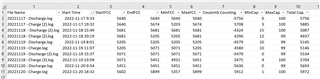
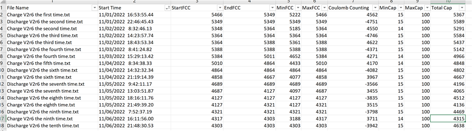
We have done all our testing on the DUT. We use our own tool for logging on the DUT. We only log the following registers: FCC, SOC, voltage, current, RM, current and temperature. I can share these logs but they only have partial information.

I will begin testing on the EVM and collect logs with BQStudio. Please let me know what other information you require to troubleshoot this problem.

Thanks

John

V2r6-FullAccess.gg.csv

  • Hello John,

    Check if the FCC matches the capacity that you can get out of the battery by doing a full constant current/power discharge.

  • HI Shirish, 

    I ran a discharge followed by a charge. The capacity matches the FCC value. 

    However, this is consistent with what we see on our device. As we continue to charge/discharge the battery, the FCC drops. 

    I will run another battery cycle to see if I can reproduce the issue. 

    20221117 - Discharge.log20221117 - Charge (2).log

  • Hello John,

    Looks like this log is with a new battery, not the FCC reduced battery

  • HI Shirish, 

    That is correct. This is the first charge/discharge cycle done after loading the golden image. I will have to run more cycles on the EVM to reproduce the issue. 

    I will review the data collected on our DUT to see if the accumulated capacity matches the FCC values. 

  • Hi Shirish, 

    I ran 5 cycles on the EVM. On the 2nd and 3rd cycles, I didn't fully discharge the battery to 0%. I discharged to 10%-15%, which is closer to our application. On these cycles, the FCC value dropped to 5000mAh. The calculated capacity loosely tracked the FCC value. On the 4th and 5th cycles, I discharged the battery to 0%. The FCC value increased to 5600mAh. Once again, the calculated capacity loosely traced the FCC value.  

    Attached are the log files. This is not the same behavior that I see on the DUT. on the DUT, we turn off the battery at 15%. I saw the FCC drop when only discharging to 15%. Does this mean the gauge is not properly simulating capacity at low capacity? 

    Below is a screen capture of the tabulated data. It shows, start, end, min, max FCC during a cycle. It also shows the calculated Coulomb counting. 

    I will share the data for the DUT testing shortly. 

    EVM Battery Cycles.zip

  • Hello John,

    Shirish is out so I reviewed the thread so far, I just wanted to confirm before diving into the data that you upload the SREC to the gauge, not just the .gg file? The .gg file doesn't contain the chem ID so you will get very bad gauging results if you only upload the .gg file.

    Also it is very common to have swings of 10% FCC depending on your load, battery resistance, and temperature. The image you shared with FCC variation looks normal.

    Sincerely,

    Wyatt Keller

  • Hi Wyatt, 

    I used the bq.fs file to load the gauge, not the gg file. 

    Thank you for reviewing our data. In the tests on the EVM, the FCC dropped when I discharged down to 15% rather than to 0%. It then recovered when I discharged down to 0%. Is that coincidental? 

    I ask about 15% because on our DUT, we shut the device off at 15%. We see a steady decline in FCC, starting at 5500mAh and ending at 4000mAh. It does not recover like the EVM tests did.

    The coulomb counting tracks the FCC. We use our own logging tool and we only log a subset of the gauge's registers. I could share those but I doubt they would be useful. 

  • Hello John,

    I will take a closer look tomorrow, some of our team is on break for Thanksgiving so were trying to get to as many questions as we can.

    Sincerely,

    Wyatt Keller

  • Hello John,

    I looked through again, I see you have load mode = 1 and load select = 1, which indicates you have a constant power load, but the logs I reviewed are constant current. This will cause some differences in the FCC calculations since we expect higher current but there actually isn't at lower voltage simulations.

    It would be more interesting to look at your Qmax and Ra tables to see how they change with each cycle (data in the .gg file). FCC has many inputs so it is harder to determine the cause if it is fluctuating. I think if you set the load select to match the load and performed a couple cycles you should see better performance.  

    Sincerely,

    Wyatt Keller

  • Hi Wyatt, 

    Thanks for reviewing the logs. The logs use constant current per Shirish's request to check that the passed charge is equal to the FCC. In our DUT, the load is constant power. 

    Attached is the GG file after 5 cycles done on the EVM with constant current load. We don't currently have the ability to retrieve the golden image from our DUT. 

    Thanks

    John

    V2r6 - After 5 cycles.gg.csv

  • Hello John,

    The gg.csv file comparison shows that Qmax dropped from 6400 to 6050 in just 5 cycles.

    You mentioned temperature rising but the discharge log shows a 1C rise only. The return ground path resistance can be accounted for by calibrating current.

    Are there any other losses? Is there anything different from the EVM schematic?

  • Thanks for reviewing. I don't know how much QMax changes on the DUT. We do not monitor that parameter. However, changing from 6400 to 6050 is not significant. I saw that the Ra Table updated as well. Can you explain those changes to me? I don't know how to convert the stored values to resistances. 

    As for the temperature change, during the EVM test, the battery thermistor is not connected to the battery. We use the thermistor that came with the EVM. That is why it is constant during the EVM test. 

    I calibrated the current for this test. But I don't see how calibrating current fixes the temperature measurement. I believe the losses in the DUT are higher than the EVM. The temperature change based on current is much higher on the DUT than on the EVM. I'm attributing that larger change to more path losses. Other than additional path losses, we follow the reference design. 

    Based on your feedback, the EVM test is not representative of what we are seeing on our DUT. I think the additional path losses on the DUT and the resulting temperature change are affecting the FCC calculation. How do we prove that? Should we rerun the EVM test with the actual battery thermistor? Or should we improve logging on our DUT? If we improve logging on the DUT, what parameters should we be logging? 

    Thanks

    John

  • Hello John,

    The algorithm needs the correct temperature to gauge correctly. Connect the battery thermistor so that the gauge reads the correct cell temperature.

  • Hi Shirish, 

    I connected the thremistor and start cycle testing.I competed two cycles, discharge first followed by charge. The discharge cycle stops when the battery's protection trips. At the start of the second charge cycle, FCC is 850mAh. During the charge cycle, it recovers to 6000mAh. Once the RemCap passed FCC, FCC tracks RemCap. 

    What caused the FCC to drop to 850mAh? We see similar behaviour on our DUT, but not to this extreme. The FCC drops at the start of the charge cycles and recovers. 

    Thanks

    John

     EVM Charge Cycles - With Thermistor.zip

  • Hello John,

    The FCC at the end of discharge does not match the FCC at beginning of next charge. What happened in between to change it?

  • HI Shirish, 

    That is the problem we are trying to solve. In this test, the battery's protection tripped and the cell went open circuit. When I applied the charger, the protection reset and the charge cycle began. From the gauge's perspective, it lost power. How does it calculate FCC after a power cycle? 

    Please note, that out DUT shuts power off at 15% but battery power is still connected to the fuel gauge. During our DUT tests, the gauge never loses power. 

    Thanks

    John

  • Hello John,

    Thanks. I did not realize that it resulted in the gauge losing power.

    So is it correct that the charger provided power to the gauge subsequently?

    When the gauge gets power again, it will then go through the procedure in TRM section 5.7.2 First OCV and Impedance Measurement. Then it will try to match the battery profile that is the closest. It should end up choosing the same profile if everything goes well.

    When you mentioned multiple cycles earlier, did each discharge cycle end up with power loss to the gauge or this was an isolated case?

  • HI Shirish, 

    yes, after the discharge, the charger restarts the system. Once charger power is applied, the battery cell protection resets and battery voltage is present. 

    In the previous tests, I stopped discharge at either 3V or 15% reported battery capacity. In this round of testing, I used the battery protection circuitry to end the test. I did this simply for convenience so I did not have to monitor the discharge test. 

  • Hello John,

    The temperature rise is significant. This internal heating will provide more power from the battery compared to when there is no internal heating. The dummy thermistor seems to have confused the gauge into thinking that there is no internal heating. I would expect the gauging to be correct when the thermistor is correctly connected