This thread has been locked.

If you have a related question, please click the "Ask a related question" button in the top right corner. The newly created question will be automatically linked to this question.

CSD87503Q3E: the rise time/fall time of CSD87503Q3E

Part Number: CSD87503Q3E
Other Parts Discussed in Thread: UCC27624

Hi together,

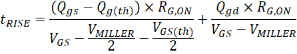
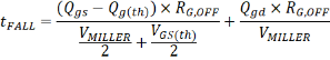
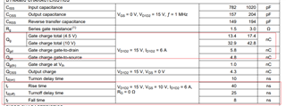
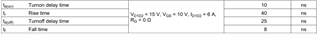
I want to design a switching circuit witch shall ensure  the rise time is the same as the fall time. But look through a lot of NMOS datasheets. The values of rise time and fall time are quite different. 

Since the process of MOS's turn-on  and turn-off all have relate to charging time for Ciss,   Why is there such a big difference in rise time and fall time.

Thanks!

Zhiyao

  • Hello Zhiyao,

    Thanks for your interest in TI FETs. The typical switching times in the MOSFET datasheet are not always indicative of actual performance in an application which is highly dependent on the external gate drive circuit and PCB layout. There is literature available on how to calculate switching times.

    A common way to estimate the rise and fall times is given in the equations below:

    The example at the link below is more complicated takes into account the common source inductance and how that affects the switching speed of the FET.

    https://www.ti.com/lit/an/slpa009a/slpa009a.pdf

    The link below explains how TI tests and specs switching parameters in the FET datasheet.

    https://e2e.ti.com/blogs_/b/powerhouse/posts/understanding-mosfet-data-sheets-part-5-switching-parameters

    Please let me know if I can be of further assistance.

    Best Regards,

    John Wallace

    TI FET Applications

  • Hello Zhiyao,

    Following up to see if your issue has been resolved. Please let me know if I can be of any further assistance.

    Best Regards,

    John

  • Hi John,

    I'm sorry for replying you late, according to the formula you provided, I tried to calculate the rise time of CSD87503Q3E.

    According to the datasheet, 

    The calculated value is 3.8ns, which is much lower than the 40ns given in the datasheet. Are there any other factors that have not been taken into account.

    Best Regards,

    Zhiyao

  • Hi Zhiyao,

    The equations I provided are estimates using the FET gate charge parameters and external driver characteristics. The thing that is not included here are inductive effects due to the common source parasitic inductance which tends to slow down the FET switching. Also, as I pointed out in my earlier response, the switching times are highly dependent on the external gate drive circuit. I am checking with a colleague to see if he has more information on the driver circuit use for this testing. I'll get back to you as soon as I have more information.

    Thanks,

    John

  • Hi Zhiyao,

    Thanks again for your interest in TI FETs. I found more information on how the switching times were tested during product development. The DUT is mounted on a daughter that is plugged into another board that includes a dual driver IC (MIC4424) with the PWM inputs shorted together and the gate driver outputs connected together. The input to the driver IC is provided by a pulse generator, the gate drive voltage is 10V and the switching times are measured with an oscilloscope. The driver IC is an older device with 3A peak drive capability. TI has low side drivers with much higher peak current capability which will result in faster switching times. For example, the UCC27624 dual channel low side driver has peak capability of 5A. See the typical application circuit on page 18 of the UCC27624 datasheet. Beyond this, I have no further information to offer.

    Best Regards,

    John

  • Hi John,

    Thanks for you patience , your answer is of great help to me.

    Best Regards,

    Zhiyao