Other Parts Discussed in Thread: PMP40960, PMP40939
Hi team,
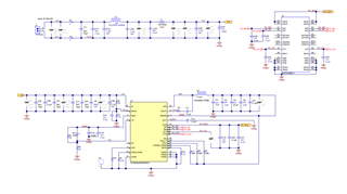
Which circuit did you use for "Figure 11-4. 2.1-MHz EMI Results (Without CM Filter)" and "Figure 11-5. 400-KHz EMI Results (Without CM Filter)"
Regards,
Ochi
Hi team,
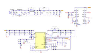
Which circuit did you use for "Figure 11-4. 2.1-MHz EMI Results (Without CM Filter)" and "Figure 11-5. 400-KHz EMI Results (Without CM Filter)"
Regards,
Ochi