This thread has been locked.

If you have a related question, please click the "Ask a related question" button in the top right corner. The newly created question will be automatically linked to this question.

TLC77: /RESET not going high with small current unless SENSE input is well over threshold

Part Number: TLC77

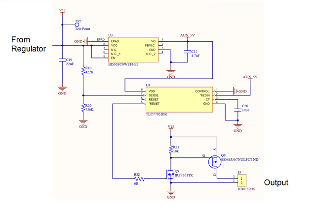
This circuit shows the TLC7705 with a resistor divider network that should provide less than 4.55V at the SENSE input when V12 drops to about 8.75V (including the internal 910k and 290k resistor divider inside the 7705). When it's above 4.55V, the /RESET line should be able to drive Q9 which drives Q8 that gates the output voltage on or off. If I take off R22 and use a wire to test the output circuit connected directly to 5V or Ground, it works fine and gates the output correctly, but as soon at it touches the /RESET line of the TLC7705 it drops to only 1mV or so and does not drive Q9 to gate the output on (it ends up having about 2.5V on the output, so it's not even driven off to ground here either). This happens only when there is a load on the output (the load is about 0.5A, 1A max), and it doesn't happen (seems to work correctly) when there is zero load on the output. I tested the available current from the Voltage Regulator when the output circuit is working (either manually by touching the Q9 input to 5V or by having the SENSE pin voltage much higher than it should need to be as detailed below), and the output current is more than enough to drive at least two times the load. The TLC7705 seemed to be the issue here - perhaps with how much current was coming into the SENSE pin? or using a TLC7705 with a resistor divider network since all examples showed the sense voltage connected directly to the SENSE pin. Since the examples only showed the TLC7701 using a resistor/divider network, we changed out the TLC7705 for the TLC7701 and we changed the resistor dividers appropriately, but we still saw the same behavior (like the TLC7701 /RESET just wasn't working or able to drive Q9 properly even though there is minimal current required there and the drive voltage required for Q9 is low). I then read another post here: https://e2e.ti.com/support/power-ma...760/tlc7701---sense-threshold-voltage-setting that mentioned the resistor/divider network current should 100x the leakage current. So I reduced the resistor/divider network to use 2.5k and 18k for R20 and R10 respectively. This still resulted in the same behavior where /reset was not able to go to 5V when the voltage on the SENSE pin is at 1.47V (but it worked okay without the load). However, when I changed out the resistors on the 7701 to have 3.6V on the SENSE pin, the TLC7701 was able to have the /reset pin go high and it would drive the output circuit correctly. This is great. However, one of the main reasons for having this voltage monitoring circuit in there is to stop the output voltage any time the V12 drops below 9V or so (or 8.75V); this doesn't happen if I change the resistor divider to be have way more than 1.1V at the SENSE input. Also, there is still the issue where it doesn't fully drive the output off either (and we see about 2.5V there) if the SENSE voltage is only a small amount over 1.1V. Ouch. I assume that I must be doing something wrong or just don't understand why the TLC77x chips don't seem to be working correctly. This is a high-priority issue, so any help or thoughts are much appreciated. Thank you.

  • Hello Brian,

    The TLC7705 has only 2mA of output current. Is this enough to drive the transistor? The current through the sense pin should be at least 0.5mA. Are you using 2.5k and 18k for R20 and R10 with a TLC7705 device or a TLC7701 device? 

    The TLC7705 is an old device. Is it possible to use the TPS3760A012DYYR ? It's 65V max Vin would remove the need for the voltage regulator.

    Best,

    Walter

  • Walter,

    Thanks for your comments.

    I had thought we were seeing only a very brief 1.6mA to drive the transistor, but I put the circuit in the simulator and it's possible that it could hit 2.2mA for the very briefest duration of time and then come back to no current at all. Could this be the issue? While I do see that the recommended maximum operating output is 2mA, it says the absolute maximum is 10mA. If it ends up going over 2mA in the instant that it switches, wouldn't the behavior still allow for it to switch? (It's so fast/transient that it's hard to get a good reading. That's why I put it in the simulator instead.) If this is the case, it's possible I could put a 100ohm resistor in place of R22 (currently 0-ohm) to limit the current even more.

    I'm not driving any current through the sense pin, it would be up to the chip to draw that current, correct?

    Yes, the 2.5k and 18k for R20 and R10 respectively are using the TLC7701 device.

    Thanks for the recommendation to use the TPS3760A012DYYR, we can look at that for future board spins. However, we already have our boards since we were not expecting this part of the circuit to have an issue. So for now, we would like to keep this footprint and try to fix what we have. The only other part I saw was the TL7705 which seems to have 5mA drive and higher/direct SENSE inputs. Is that one considered old as well?

    Please feel free to let me know your thoughts on this. 

    Best regards

  • Hi Brian,

    It sounds like the reset output current might not be the problem. 

    Can you try further reducing the voltage divider resistances to increase the current through the voltage divider?

    The TL7705 is also an old device.

    Best,

    Walter

  • Walter,

    With the TLC7705, dropping the voltage divider to use 1K resistors for both R10 and R20 did not have show any difference. The sense pin shows 6V, but the /RESET is still not going high (and the RESET is not going low either). With approximately 6mA running through that 1K resistor, it should allow the SENSE pin to be able to draw what it wants (you mentioned up to 0.5mA). I wouldn't think I should go any lower than that, right? (Or do you want me to try 500-ohm resistors on R10 and R20? It seems a bit much for a voltage divider, but I'm not sure what else to do here.)

    Just for good measure, I swapped the 0Ohm on R22 for 100Ohm but it also didn't make a difference. 

    What voltage should I see on CT? With the 10uF, it fluctuates between 1.0 and 1.3V. If I swap it out for 0.1uF, it's at about 1.1V. Still does the same thing on the output, though (not having /RESET go high).

    Let me know any other thoughts you have here. Thanks again. 

  • Hi,

    The problem is not the input current then. Have you tried replacing the device in the circuit? I am working with my team to resolve this. Thank you for your patience.

    Best,

    Walter

  • Walter,

    I replaced the device with a TL7705 (not TLC) with 1K resistor dividers, and I removed the output chain. This doesn't behave as expected. The sense pin has 5.8V on it. However, it has the RESET pin at 2.37V and the /RESET pin is ground. Since we're using 5V input as VCC, I would at least expect the output to be VCC-1.5V as per the datasheet. I will try again with the TL7705 on another board. To answer your question in regards to trying other TLC devices, yes - we have tried several different boards (chips) as well. If you have any other ideas, please let me know. Thanks so much.

    Best regards,

  • Thank you for your patience. Sorry, but we do not have any other suggestions at this point. I will circle back if any new ideas come up.

    Best,

    Walter