This thread has been locked.

If you have a related question, please click the "Ask a related question" button in the top right corner. The newly created question will be automatically linked to this question.

TPS65150: stability issue with moisture/water condensation

Part Number: TPS65150

Hi, 

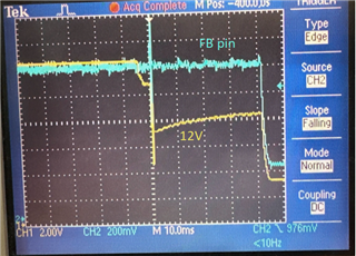
We have an application circuit that fails moisture testing despite having acrylic/urethane conformal coating. (soak in 30-60C 95% moisture for 10days, running fine, it fails (shuts down it self) after taken out to room temperature for 20min, so minor condensation might be present).

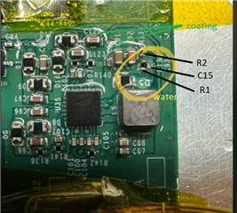
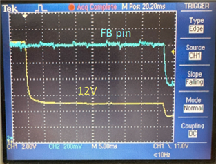
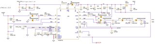
We tried and reproduced the problem by putting a drop of water on the circuit on R1, C15, L1, D1 (conformal coated) (reference to the ref.des. on datasheet) without any load current, the failure happened immediately. This lead us to suspect that the parasitic capacitance of water may be disturbing the circuit and the stability margins may be on the edge. We have been using the recommended values on the datasheet (will list below). To improve stability, we plan to reduce the size of R1, R2 to 160K/16.9K and C15 to ~120pF (haven't test it)

Question: Is there anything else that can help to maximize the stability of the circuit to make it less suspectible to parasitics or external disturbances?

our setup for reference: 

Input: 3.3V

Output: 12V, 25V, -10V

L1 = 4.7uF, C9 = 470pF, R9 = 33K, R1 = 820K, R2 = 86.6K, C15 = 22pF,   

R3 = 620K, R4 = 75K, R5 = 510K, R6 = 26.1K

Thank you,

Borui

  • Hi Borui,

    According to your description, I suspect short circuit is caused by condensation water.

    So have you checked the acrylic/urethane conformal coating yet? I think firstly we have to make sure whether this coating is fully protecting the circuit or not.

    BR

    Patrick

  • Thanks for the response Patrick.

    Yes. After that failure happend, we did suspect somewhere were shorted, so we took the board out and removed and redo conformal coating on 2 boards. 1 with acrylic, the other board with 2 layers (very thick) urethane coating. Both failed the water drop test at the same location. We did the coating and curing carefully making sure smooth surface and no visible bubbles etc. We are not saying it's impossible for the water to get in, but I think it's pretty unlikely. 

    Below are some pictures, first picture indicates the water drop location and size/shape. The second and third are waveforms where we probe outside the water drop area on VS and FB (FB is probed on a via near U35.4 so it shouldn't affect the water test). They are from 2 runs of the same test, the difference is probably due to water shape/size. but in both cases, 12V dipps immediatly and it seems after the Fault delay timer, the chip shuts down. 


    Let me know if you need more information. 

    Thank you,

    Borui

  • Hi Borui,

    I need to check internally and give you feedback tomorrow.

    Sorry for the inconvenience and thanks for your patience.

    BR

    Patrick

  • Hi Borui,

    Could you please capture the current waveforms? Either the inductor current or the output current is okay. This will help to judge whether there is an overcurrent after water drop.

    BR

    Patrick