This thread has been locked.

If you have a related question, please click the "Ask a related question" button in the top right corner. The newly created question will be automatically linked to this question.

BQ76PL536A: Balancing affects cell voltage measurement

Part Number: BQ76PL536A
Other Parts Discussed in Thread: BQ76PL536EVM-3

Hello TI team!

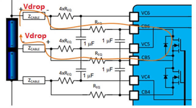
Currently we are developing a custom BMS based on bq76pl536A IC and 32 series cell modules. When the balancing circuit is enabled, the adjacent cell voltages voltage measurements (if n cell is balancing, n-1 and n+1 are adjacent) doesn't match actual cell voltage (measured via external voltmeter). Unfortunately, I can't share any schematics, but they are based on the application notes you provide.

We've spent a while investigating this issue but have no clue what can be happening. 

  • Actually, the cell being balance also has a bad measurement. From 3.555V it drops to 3.294V in the board, but the cell voltage in its terminals its 3.544V

  • HI Andres,

    By actual cell voltage measure by voltmeter, are you measuring on the pins directly? The cell voltage measurement are expected to not match the actual cell voltage during cell balancing, that's why normally we would suggest to pause the cell balancing and wait voltage settle, before reading the cell measurement data. 

    When Cell balancing is on, the CB current flowing through the wire and connector will form a certain voltage drop and will affect the cell measurement. 

    ADC itself accuracy should not be affected during cell balancing, you can measure the voltage on the device pins directly and compare to ADC readings, so to confirm this.

    Hope this helps.

  • Ted,

    the device pins and ADC measurements are the same, which is good and tells me the device and firmware is working as expected.

    I understand the reasoning on why the balanced cell measurement should differ but why are adjacent cell measurements afflicted? I have tested this on the bq76pl536evm-3 board and same effect is shown.

    The following and previous cell of the balancing one are always affected, and we don't understand why. If you need any data or logs showing I can DM them to you. 

  • HI Andres,

    See below picture, assume the Zcable the same resistance, when cell balance enabled, the CB current flow through the Zcable will form a voltage drop says Vdrop as below. So the Cell6 measurement would be VC6-5= Vcell6 - 2Vdrop; Similar the VC5-4 = Vcell5 +Vdrop.

    So you can see it would affect the balancing cell, and the adjacent cells including both following and previous one.

    Let me know if this clarify your question

  • It's the same effect we've noticed in our boards and evm board. As you explain, this is also due to Req balance resistor, and lower resistance should drop the voltage even further. Is there any way we could avoid this effect or as you state, configure the chip to compensate this effect.

    Thanks and greetings!

  • Andres,

    You can decrease the resistance to decrease the effect but you know it cannot 100% resolve this issue and lower resistance means poorer hotplug performance. No perfect way to 100% resolve this issue. Yes, you can compensate the IR drop by your MCU algorithm, but because the resistance is various at temperature so your compensation will not be too accurate. If your system accepts this temperature drift error, please just go ahead to compensate it. .