We are using UCC256404 in one of the Project. IC functions as per expectation. One of the requirement of Power supply is to provide 22A at step loading. No Load (0A) to 22A sudden step change.
During no load, IC enters in burst mode and we observed, if step load is applied then sometimes o/p collapses completely and then recovers back immediately (within a sec) and sometimes it does not collapse and provides good transient response.
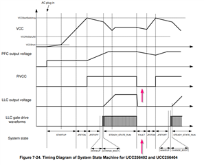
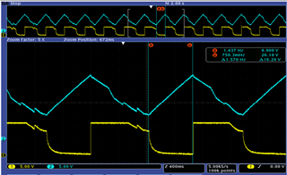
Further detail investigation showed that during no load burst mode operation, RVCC is pulled to low. RVCC is a square wave with 1sec Frequency. see below image for details.
![]()
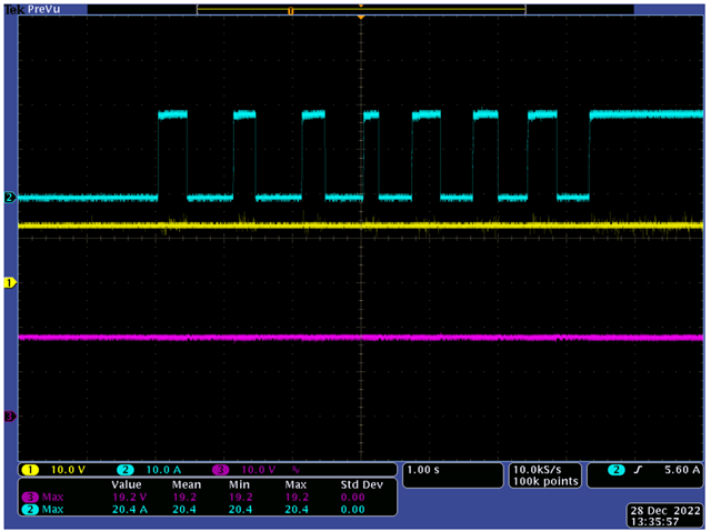
We identified at 15mA o/p Load RVCC is continuous and hence when we connect 1k resistor across o/p the RVCC remains ON always and Converter gives excellent transient response for multiple step loads in shrt time which is way above the actual requirement. See below Waveform with 1k added across 18V o/p
Blue : op current, Yellow: RVCC, Purple :Vout
with Above Details there are few questions
1. When IC is operating in burst Mode, why RVCC is fluctuating. I went through datasheet again to see if i can find any reference, but i could not find anything related to RVCC pin behavior during burst mode operation. It is Normal ?
2. we have a NTC based over temperature detection circuit, which turns OFF LLC Converter by Pulling Down BLK pin of UCC256404. This circuit misbehaves when LLC Stops operating. as RVCC also varies and goes to Zero the hysteresis designed for the Over temperature ckt does not operate.
What needs to be done to make Sure RVCC will keep its regulation level, if UCC256404 is powered.