This thread has been locked.
If you have a related question, please click the "Ask a related question" button in the top right corner. The newly created question will be automatically linked to this question.
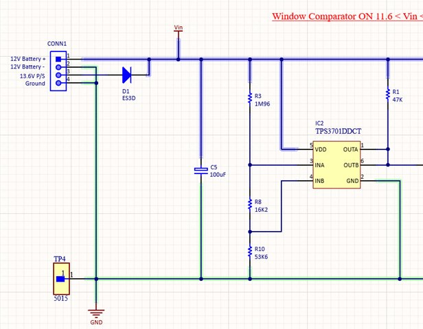
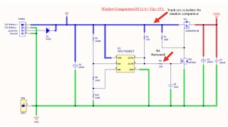
Please find attached the image of the window comparator circuit using TPS3701DDCT to monitor voltages of 11.6V to 15.1V from a Battery.
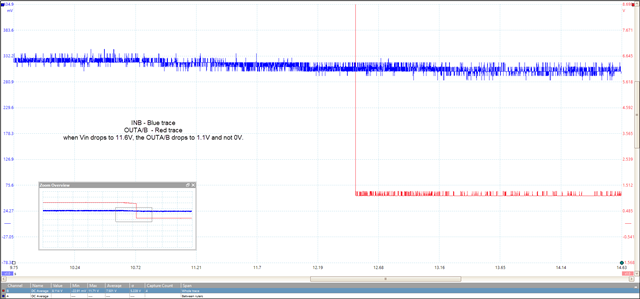
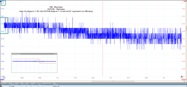
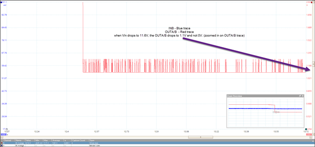
The comparator monitors the same voltage as the Input voltage.
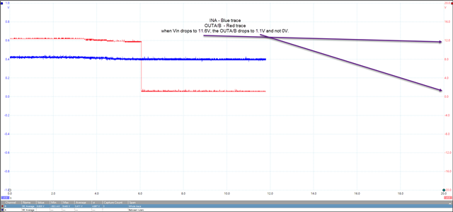
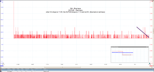
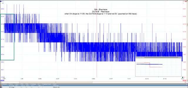
However, the comparator output produces 1.3V instead of 0V once the voltage falls shooting up the current consumption(~40mA) upon reaching the under-voltage threshold voltage and the same occurs upon reaching the over-voltage threshold.
Please let me know what is causing the issue and how can I fix it?
Hi Pallavi,
Thank you for your question. Are you able to provide a scope shot of INA, INB, and OUT during the failure?
Jesse
Please find below the scope shot of Input A & B and Output during the failure.
When the Vin drops to 11.6V, the output voltage drops to 1.1V and not 0V.
Hi Pallavi,
From the datasheet, the maximum VOL (voltage output low) is suppose to be 250mV.
One thing I can immediately that could cause this issue is the 100uF cap on the VDD, could you please try to testing by replacing with a smaller cap, around .1uF?
I will also consult with our design team for other possibilities.
Jesse
Hi Jesse,
Thank you for your reply. I replaced C5 tantalum cap in a board where the window comparator was totally isolated (Resistor R4 removed and a track between R1 & R2 cut), the output had dropped less than 10mV which is good.
However, on another board where the windows comparator circuit is not isolated, I still see the same behavior of OUTA/B being held at 1.1V. I have removed only C5 on this board. I am wondering if 100uF at Vsys is creating issues? If so, what would be the recommendation?
Hi Pallavi,
Looking at the non-isolated schematic, please remove C8 as well.
Jesse
Hi Jesse,
I removed Cap C8 but the output voltage has not changed, its still at 1.11v.
Regards,
Pallavi
Hi Pallavi,
I have forwarded your findings to our design team, I will update once we have the information.
Jesse
Hi Pallavi,
Sorry for the delay, I have been working on simulations and testing for your issue. I have not been able to replicate the issue.
When you run the test on the non-isolated board, is it attached to the Vsys? According to design, it maybe possible that there is another path to your output pull-up resistor that is causing this issue.
Jesse