A related question is a question created from another question. When the related question is created, it will be automatically linked to the original question.
If you have a related question, please click the "Ask a related question" button in the top right corner. The newly created question will be automatically linked to this question.
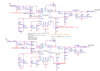
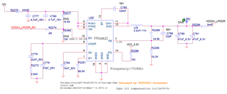
TPS54622: TPS54622 Schematic design check (Apply to NAND & LPDDR)
Please look at the "Input Sheet" of the attached Excel calculator that was used to review your schematics. There are 3 columns each contain data and comments about one of your schematics.
Please pay full attention to the Cells in red (warnings). Let me know if these warnings are clear or you require further assistance.
If this addresses your question, please set the status of this post to resolved.
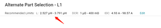
when I used same parameters both on "Webench Power Design" and Excel you provided, for example, I used 2.2uH inductor and 500KHz fsw when output 1.2V, the Excel shows checking pass but "Webench Power Design" shows I need use 2.5~3.8uH inductor. So, which one should I refer to?
For 1.2V, a 2.2 uH inductor is fine at 500 KHz. With this choice of inductor value Kind is 0.3. We recommend Kind of 0.2 to 0.5.
The Kind (line 41) setting on the "DeviceCalculator" sheet of the Excel tool has an effect on the inductor value.
The higher is the Kind, the current ripple will be higher, the transient response will be better, and the L value will be lower.
You have 3 options, and they are all good options:
1) Just rely on Webench.
2) Play with the Excel tool (Kind) and let me know if you have any questions. The calculator as I have sent you just provides warnings on the issues with your current design. To get to the optimal schematic values, you still need to interact with the Excel tool. As you already did.
3) Provide us with the max current and transient requirements for each rail and I will recommend the exact values for all components.