This thread has been locked.

If you have a related question, please click the "Ask a related question" button in the top right corner. The newly created question will be automatically linked to this question.

TPS1HB08-Q1: Reverse polarity protection: Is IGND maximum allowable reverse current?

Part Number: TPS1HB08-Q1

Hi team, 

We want to make reverse polarity protection. Is "Reverse ground current, IGND = -50mA" maximum allowable reverse current?

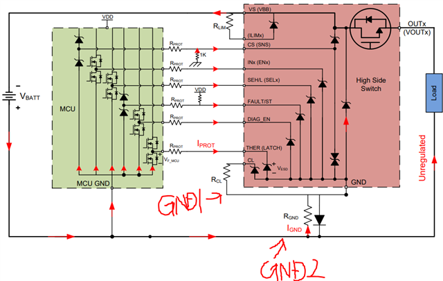
Do you recommend 1-kohm as RGND for both of TPS1HCxx-Q1 and TPS1HBxx-Q1 for "Figure 2. Diode-Resistor Ground Network" shown in lower link?

https://www.ti.com/lit/an/slvae55/slvae55.pdf

Regards,
Ochi

  • Is "Reverse ground current, IGND = -50mA" maximum allowable reverse current?

    For which pin do you refer to IGND? How much reverse current available for lower pins on TPS1HB08-Q1?

    • SNS PIN
    • LATCH PIN
    • SEL1 PIN
    • DIA_EN PIN

    Regards,
    Ochi

  • Hi Ochi-san,

    The IGND refers to the current flows directly into the IC's GND pin, and 50mA is the maximum allowed reverse current. 1k is our recommended resistor, as in reverse battery situation, 18V will result in 18mA of current into GND pin, which is in range.

    For the I/O pin, the reverse current should be below 1mA. It's recommended to have 5k-10k series protection resistor to limit the reverse current flow.

    Please let me know if you have additional questions.

    Regards,

    Yichi

  • Hi Yichi, 

    Thank you, I understood. 

    Which GND1 or GND2 shown in lower picture should TPS1HB08-Q1 I/O pin pull down resistor be connected to? We do not use SNS, LATCH, SEL1, DIA_EN and want to pull down to GND. 

    Regards,
    Ochi

  • Hi Yichi

    I guess unused SNS, LATCH, SEL1, DIA_EN pins should be pull down to GND1 shown in above figure. Is it correct?

    Then, are RPROT for I/O pins (LATCH, SEL1, DIA_EN) really needed? Could I use just one 5-10kohm as RGND with unused I/O pins short to GND1? 

    Regards,
    Ochi

  • Hi Ochi-san,

    The pins you listed all have internal pull-down resistor except SNS pin. You can leave them open if not using. If an external pull-down is needed, pull-down to GND1 is preferred over GND2 as that's the GND the chip is referring to. However, pull-down to GND2 will still work. For SNS pin, if not used, you can connect to GND2 with a 1k resistor, as the SNS output is always referring to the system GND for voltage readback.

    It's recommended NOT to increase RGND over 1kohm, as during the normal operation, it might cause too much voltage drop across the resistor, and causing too much voltage different between GND1 and GND2. If voltage difference is large, then the signals referred to GND2 will be read incorrectly by the IC and vice versa. If an external pull-down is applied to GND1, you can have an extra resistor connected to GND1 while keeping RGND at 1k.

    Hope this makes sense and let me know if you have additional questions.

    Regards,

    Yichi

  • Hi Yichi, 

    Thank you so much. 

    About pull down resisor RPROT between GND1(please refer to previous figure I sent) and I/O pins (LATCH, SEL1, DIA_EN), how much resistance do you recommend? Just 1kohm is enough or do we need still 5-10kohm? GND1 voltage should go -0.7V due to intenral ESD diode between GND pin and VS pin, is it correct?

    Ochi

  • Hi Ochi-san,

    Yes 1kohm should be fine for the pull-down to GND1. The GND1 voltage should be 0.7V during reverse battery event due to the diode direction. Could you elaborate on where did you get the -0.7V?

    Regards,

    Yichi