This thread has been locked.

If you have a related question, please click the "Ask a related question" button in the top right corner. The newly created question will be automatically linked to this question.

TPS2116: ESD Input Protection / TLP Failure Voltage for IEC 61000-4-2

Part Number: TPS2116
Other Parts Discussed in Thread: TPS2121, TIOS102

Hi,

I'm planning on using a TPS2116 in my design to select a system voltage between one of two sources: 

1) 5VDC from the output of an AC-DC PSU.

2) 5VDC, directly from a USB-C input.

I'm looking to add some ESD protection diodes to the inputs as per IEC 61000-4-2, but I'm uncertain whether adding an ESD diode on these lines will be sufficient to protect the TPS2116?

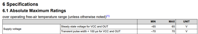
The absolute max limit in the datasheet for VIN1 and VIN2 is stated as 6V, however after watching your (excellent!) video "1.6 ESD Essentials: How to Select ESD Protection", it advises that:

"Keep in mind, TLP failure voltage of a device is not the same as the absolute maximum voltage rating of the device. Absolute maximum voltage is a DC voltage, while TLP is a 100-nanosecond transient. I would also like to note that finding the required clamping voltage of a system is not always easy."

Do you have information relating to the TLP failure voltage for the TPS2116?  Is it possible to protect the inputs as per IEC 61000-4-2, or should I move to use the TPS2121?

Thank you!

  • I should clarify on my previous post around my uncertainty:

    The absolute max limit in the TPS2116 datasheet for VIN1 and VIN2 is stated as 6V.  Common TVS diodes rated for 5V lines typically have a Vclamp of 10V (Ipp=1A) or ~33V (Ipp=18A), (Vclamp being a function of the diode's dynamic resistance and peak pulse current). 

    I'm uncertain whether a TVS diode rated for IEC 61000-4-2 (and IEC 61000-4-5 for that matter) with above Vclamp voltages is suitable for protecting the TPS2116 Vin pins?


  • Hi Robin, 

    The ESD protection used must result in all voltages seen at the device to be compliant with the specifications in the datasheet which in this case is an absolute maximum voltage rating of 6V. 

    Additionally with regard to layout, the rule of thumb is the that diode should be placed as close to the source of the transient as possible, usually this is the connector.

    Best Regards, 

    Elizabeth 

  • Thank you for the response Elizabeth!  Before watching the "1.6 ESD Essentials: How to Select ESD Protection" video I'd have agreed that not exceeding the absolute maximum voltage from the datasheet (6V) would make sense, but I now don't understand the statement made in that video:

    ""Keep in mind, TLP failure voltage of a device is not the same as the absolute maximum voltage rating of the device. Absolute maximum voltage is a DC voltage, while TLP is a 100-nanosecond transient."

    Am I missing something?

  • Hi Robin, 

    I reached out to the ESD team internally to get their feedback here. 

    However, with regard to the absolute maximum for our devices in the power mux portfolio, these are not really DC voltages recommendations. We do not recommend exposure the absolute maximum voltage at a DC level. Exposure to absolute-maximum-rated conditions for extended periods may affect device reliability. Whereas any operation outside of the abs-max specs could result in a device failure due to overstress.

    Operation in the abs max range is additionally not ideal as there could be significant variation(timing, on resistance, response to inputs, etc) from datasheet specifications as these were characterized under the recommended operating conditions.

    Best Regards, 

    Elizabeth 

  • Hi, Just wondering if there's been any further information regarding the confusion between TLP failure voltage and absolute maximum voltage rating of this device?

    It's still not clear how TLP failure voltage and absolute max voltage rating differ?

  • Hi Robin, 

    Let me follow up with that team and I'll give you an update tomorrow. 

    Best Regards, 

    Elizabeth 

  • Hi Robin, 

    I've been able to gather some clarity on this topic. 

    As a general rule of thumb, it’s always good to try to have your diode clamping voltage below the abs max rating of the IC it is protecting. However, sometimes this is not possible. For example, the operating voltage of an IC signal line might be 3.3 V and the abs max is 4 V. In that case, your diode would need to have a Vrwm of 3.3 V and a clamping voltage under 4 V, which is extremely hard to do. However, like the video stated, that is the DC abs max. Most of the time, the IC will be able to handle higher voltages at shorter amounts of time. For example, see how the TIOS102 datasheet states the steady state (DC) abs max for the OUT pin at +/-65 V and the transient abs max for pulses < 100 us at +/- 70 V. So the diode clamping voltage protecting the OUT pin would need to be lower than 70 V, not 65 V.


    Since we do not specify a transient pulse width <100us, you will have to reference our maximum steady state voltage of 6V. 

    If you are looking for IEC 61000-4-2 protection, you will require external circuitry to meet this specification 

    Please find the ESD portfolio here: https://www.ti.com/interface/circuit-protection/esd-surge-protection-ics/products.html and for faster ESD support please create a new post with one of those devices tagged. 

    Best Regards, 

    Elizabeth