This thread has been locked.

If you have a related question, please click the "Ask a related question" button in the top right corner. The newly created question will be automatically linked to this question.

TPS75333-EP: Similar but faster part

Part Number: TPS75333-EP
Other Parts Discussed in Thread: TPS74801, TPS753, TPS7A8300, TPS748A

We have used TPS75333QPWP in a previous application and are looking at using it in a new application. However, the RESET timeout delay of 100ms is a little longer than we would prefer. Is there perhaps a similar part (voltage, current, etc.) that may have a shorter RESET timeout delay?

  • Hi Bob,

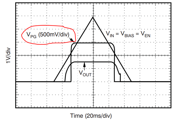
    I would recommend trying out TPS74801 which has similar specs with a faster power-good signal.

    Also, for reference here is a quick spec comparison between the two:

      TPS753 TPS74801
    Iout(Max)(A) 1.5 1.5
    Vin(Max)(V) 5.5 5.5
    Vin(Min)(V) 2.7 0.8
    Vout(Max)(V) 5 3.6
    Vout(Min)(V) 1.5 0.8
    Fixed output options(V) 1.8, 2.5, 3.3 Adjustable
    PSRR @ 100
    KHz(dB)
    17 28
    Noise(uVrms) 60 20
    Accuracy(%) 2 2
    Dropout voltage
    (Vdo)(Typ)(mV)
    160 60
    Iq(Typ)
    (mA)
    0.075 1
    Output capacitor type      Non-Ceramic Ceramic
    Thermal resistance
    θJA(°C/W)
    43 44.2(VSON), 36(VQFN)
    Operating temperature
    range(C)
    -40 to 125 -40 to 125
    Package size: mm2 42 mm2: 6.4 x 6.5 (HTSSOP|20) 25 mm2: 5 x 5 (VQFN|20), 9 mm2: 3 x 3 (VSON|10)
    Packages HTSSOP|20 VQFN|20, VSON|10

    Regards,

    Andres

  • Thank you for the reply. This part does look interesting, but I'm having a hard time figuring out the timing as I don't see anything in the datasheet other than the figure you provided. Using this for 3.3V, what would the threshold voltage be for PG to go high and what would be the timing delay for that to occur? This is an FPGA application and need delay for associated PROM to be "ready"

  • Hi Bob, 

    From the image shared by Andres, we can observe that Vout~1.5V, and as with the majority of our devices with a PG functionality, the typical threshold 90% of Vout with a min and max of 85% and 94%. In this case we can approximate the delay to be ~10ms. This will also depend on the rise time for Vout since the decice has a Soft Start function that will set the turn on response with an external capacitor (Css). 

    I highly recommend looking into TPS748A, which is a newer device similar to the TPS748. 

    Lastly, we could measure this in bench, if needed, and with a given set of conditions to emulate as close as possible the customers use case.

    Best, 

    Edgar Acosta 

  • As I look at this more closely, using PG does support faster timing but does also allow for some uncertainty in the timing with soft start, load, etc. The TPS7533 has the RESET output in addition to the PG that provides the somewhat more predictable timing, but at a much longer time. Do any of the newer parts include the RESET output but at less than 100ms (the 10ms number above is appealing)? If not, is there a way to make the PG timing more predictable?

  • Hi Bob, 

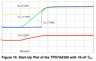
    When using the soft start feature the startup time is calculated by: tss = (VREF × CNR/SS) / INR/SS, this sets the rise time for Vout. Here is a quick example using TPS7A8300:

    This is taken from the Pros and Cons of Using a Feedforward Capacitor with a Low-Dropout Regulator (ti.com) Application note, but this can be used to have a better picture. One can always use the total tss as a worst case in timing. 

    We can think of PG being a newer version of RESET, and for TPS748A, there is a typical spec for startup if no Css is used, therefore, if this 170us is used, then when Vout reaches 94% this would be ~160us, or if the 10nF spec is used then it would be~1.13ms

    Best, 

    Edgar Acosta

  • Edgar - thank you for the additional information. I wanted to be sure I'm understanding correctly. Is the 10nF spec of 1.13ms the time from Ven going high to PG going high? If so, we are looking for the timing from when Vout hits a specific voltage until PG goes high. I need at least 300us from when 3.3V reaches approx 2.3V until PG goes high (but hopefully less than 100ms as that significantly impacts my startup timeline). If we know rise time, is it just calculating the time from 2.3V to 3.1V, at which point I'm guessing PG goes high very quickly (ns?)? I see the where CNR value comes from. Where does the INR value come from (and is it also variable)?

    Thanks.

    Bob

  • Hi Bob, 

    The 1.13ms timing is related to the TPS748A and not the picture shown. That is for the TPS7A83, and it was to demonstrate how PG triggers once Vout reaches ~90% of its set value. I apologize if this caused any confusion. 

    So PG will assert high once Vout reaches a certain value and typically it is close to 90% of the set value, it could be 3.3V as in your case. The ISS current will not vary, this is a constant value that is always used for the soft start circuit. This allows to adjust the startup time by just placing an external capacitor. 

    So staying with the previous 10nF example, it will take Vout 1.2ms to reach its 3.3V. When Vout reaches ~2.97 V (90%), this will then translate to ~1.13ms in which PG will assert high. The rise of PG is independent of all this and it should rise quick almost as a step. Having said that, 2.3V is ~69.69% of 3.3V, this should be at ~0.836ms, giving an approximate window of 1.13ms-0.836ms~0.2940ms from 2.3V to the point when PG triggers. 

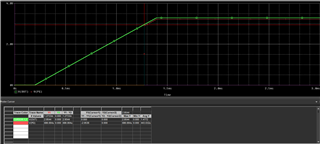
    Here is an example using the TPS74801 model: 

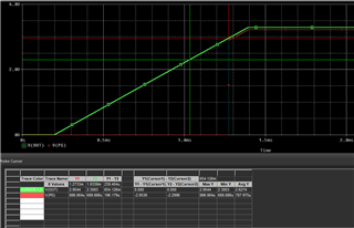
    Notice that Vout~3.3V and VPG rises at ~90% : 

    It takes Vout ~1.2ms to reach 3.3V and PG rises at ~1.07ms. 

    If we now look at the difference from 2.3V to the point where PG rises we see a difference of 0.239ms

    Now, the simulation is not perfect and will have some inaccuracies, but overall it gives us close enough estimations and it shows the behavior of PG. 

    Best, 

    Edgar Acosta

  • Edgar,

    Thank you so much for the explanation. The TPS748A looks like it can have Css up to 100nF. Is that correct? Is it as simple as taking your numbers x10 to get approximate numbers for 100nF? I missed it before, but I now see Iss is 7.5uA Typical. Is there any information regarding tolerance on this (I guess the max is more important here as that would reduce time)? Since all is approximate, I would like to give myself some buffer but also don't necessarily want to "max out" and make start-up timeline way longer than it needs to be.

    Thanks.

    Bob

  • Hi Bob, 

    Yes, the maximum recommended value for Css is 100nF. 

    Is it as simple as taking your numbers x10 to get approximate numbers for 100nF?

    In some sense, yes, since tss=(Vref*Css)/Iss and assuming Vref and Iss are always 0.8V and 7.5uA. 

    We know in reality that Vref and Iss have some tolerance (min and max). 

    If current increases, then the time reduces since they are inversely proportional, so in the case that the maximum Iss is 10uA (as an example) now your time is 8ms compared to 10.7ms when using a 100nF capacitor as an example. 

    Let me look for the tolerance in Iss and get back to you once I find such data. 

    Best, 

    Edgar Acosta

  • Thanks Edgar.

    While you're looking for Iss current tolerance, maybe you could answer another question. I have looked in the data sheet and I'm not seeing a curve, but I'm guessing the output current varies with input voltage and output voltage. Our worst case is with running the part of off 5V (I guess 5,25 max) with an output voltage of 1.0V. What output current can we get over temperature? 

    Thank you. 

    Bob

  • Hi Bob, 

    I found some data on the Iss spec, and it seems that it doesn't deviate much from the 7.5uA, meaning that the accuracy is very tight, however, I have reached out to the team to confirm this and make sure that the data I am looking is also accross temp. 

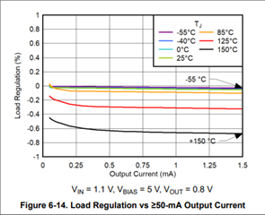
    In regards your second question, correct me if I am wrong, but is seems you are asking for Load Regulation or Power Dissipation? Can you elaborate more what you mean by Iout varying with input and output voltage? If it is the Load Regulation then Figure 6-14 shows this: 

    If it is Power Dissipation, then this will also depend on the PCB layout and load, but the output current should not vary with input and output voltage. It could impact on how much headroom is needed, meaning that it will determine your dropout voltage. 

    If that is the case then at maximum current 1.5A, Vout of 1V, you would need a Vin of ~1.135V, or a 1.5V to provide more than sufficient headroom and keeping a decent power dissipation. 

    However, if thermals is the concern then, assuming standard JEDEC numbers, max Load and 5.25V worst case and continuous operation , Pd=6.375W, which is quite a lot of power dissipation. This corresponds to a 300C rise, which would trigger Thermal Shutdown immediately. 

    With the given conditions, lets assume maximum ambient temperature, Ta=125C, then Tj~150C with a power dissipation of 0.5W, therefore, Iout should not exceed ~0.1176 A. This is at the edge of operating at the maximum recommended temperature which would put the device close to thermal shutdown but still in a safe area to prevent overheating and damaging the part. 

    If Ta=25C, to reach a Tj of 125C, then Pd~2.2558, meaning Iout~0.53A

    Let me know if this is what you were looking for. 

    Best, 

    Edgar Acosta

  • Edgar,

    My apologies for not asking more clearly. The question was in regards to thermal. I was trying to determine if the output current capability was determined solely by junction temperature or if there might be other constraints as well. As you show, 1.5A at that Vin and Vout over full ambient would not be practical so we would need to derate the output current. In your example, you show 2.25W at ambient. So I can dissipate 2W (or potentially more) provided we maintain junction temperature below 150C? 

    Thanks.

    Bob

  • Hi Bob, 

    No worries, it seemed I was on the right track with the thermals approach. 

    The recommended maximum for Tj is 125C, although the absolute maximum is 150C. We can only guarantee what we have listed in our DS. 

    Using the Tj of 150 was just used as an example to prevent thermal shutdown and show some numbers. This will vary specially since Rja will be also impacted by the layout of the PCB. 

    It is true that at ambient you could potentially dissipate more than 2W, taking into account the layout for the PCB. And as mentioned above, we can only guarantee what it is listed on the DS. 

    Another thing to consider, continuous operation under such conditions is not recommended as it has a direct impact on the long-term reliability of the device.

    Best, 

    Edgar Acosta

  • Hi Bob, 

    We can expect a min of 5uA and a max of 11uA across temperature (-40C to 150C) for the Iss current being 7.5uA the typical value.

    Best, 

    Edgar Acosta

  • Edgar,

    I appreciate all your help. You mentioned the TPS748A versus the TPS748. Other than TPS748A being the newer part, are there any significant differences?

  • Hi Bob, 

    Although performance between both parts is very similar, they are different silicon. There were some improvements on its transient performance, the Soft Start feature and thermals. 

    Best, 

    Edgar Acosta

  • Can we use any of the TPS748 data with the TPS748A? As an example, the TPS748 has a formula for the feedback resistor values and a table for certain common voltages, but the TPS748A does not? If we can't use the TPS748 data that is missing from TPS48A, where would we find that data (without having to bother you) Slight smile

  • Bob, 

    Yes you can use portions of the TPS748 DS. We are working on the DS to include those missing portions to avoid having to look at the TPS74801 device. 

    The formula is the same for both devices and the table for Vout resistor values should provide same results. 

    Feel free to reach out if any other questions come along. 

    Best, 

    Edgar Acosta