Other Parts Discussed in Thread: UC3854, , UCC2818, UCC28064
Hi Experts,
Customer would like to continue this thread for additional request:
This thread has been locked.
If you have a related question, please click the "Ask a related question" button in the top right corner. The newly created question will be automatically linked to this question.
Hi Experts,
Customer would like to continue this thread for additional request:
Hi ARchie,
Thank you for posting the query on UCC28513. I will go over the query and get back by tomorrow.
Regards,
Harish
Hi Archie,
I was trying to do more analysis and found that the PFC controller in UCC28513 is almot same as UCC2818 and I thought it would be good use this as reference. Based on this I have attached the MATHCAD calculations file which can be directly used. Please try the attached and let us know your observations.
Mathcad - UCC3817-UCC28513 Design Procedure.pdf
Since you do not have Simplis, we have a good news for you is we have a UCC2818 TINA/PSPICE model. But the model is unencrypted. So if you have an NDA we would be able to share this for simulation and evaluation purpose. Please let us know your inputs.
Thank you
Regards,
Harish
Hello Harish,
I am the Hardware Engineering Manager at Listen. Alex Wood, who has been corresponding with Archie, is working for us a consultant on this project.
Would it be possible for TI to initiate the NDA between TI and Listen so we can get the UCC2818 TINA/PSPICE model?
Thanks,
Al Flint
Hi Mr. Flint,
Thank you for the reply.
I will be sharing the TINA/PSPICE model with Archie.
Regards,
Harish
Hello Harish,
Alex responded:
Hi Archie, Alex
Thank you for the reply with the new results.
The following component designators are based on UCC28513.
R2 can be kept at 0.43ohms
R8/R12 be 3kohms
R13 and C6 at 3.23k and 4.9nF
All others look fine. But the change in frequency seems strange to me and happens irrespective of inductor. I will have to look into it further before commenting on it. I will get back on this issue after consulting the team.
Can you please update based on the above component values? Also for the 220V can you try increasing the load from 25W to 60W or higher?
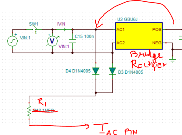
Also is it poosible to feed IAC directly from AC supply as shown below:

Between what does Q5 and Q6 in PSB refer to in the board / results document?
Regards,
Harish
Thank you, Harish.
Our customer, Alex, will implement the recommendations and report back. Refer below for this response to your follow up:
Between what does Q5 and Q6 in PSB refer to in the board / results document?
Q5 and Q6 refer to transistors used on downstream of PFC stage. Currently they are removed, and resistors are connected to PFC output as load. Sorry for confusion. They will be removed from the report.
Thank you.
73,
Alex/Archie
Hi Alex/ Archie
Thank you for the reply.
Makes sense now. Please let us know your findings on the latest suggestions.
Regards,
Harish
Hello Harish,
Happy Monday.
Hi Archie,
I am going through the results and will get back to you by tomorrow.
Thank you
Regards,
Harish
Hi Alex/Archie
Thank you for sending the detailed results. Sorry that moving the sensing circuit for Iac before rectifier did not work, I was suggesting this as the input current seemed to have some phase difference.
The results look interesting. I have been trying to look into this yesterday and here are my initial comments:
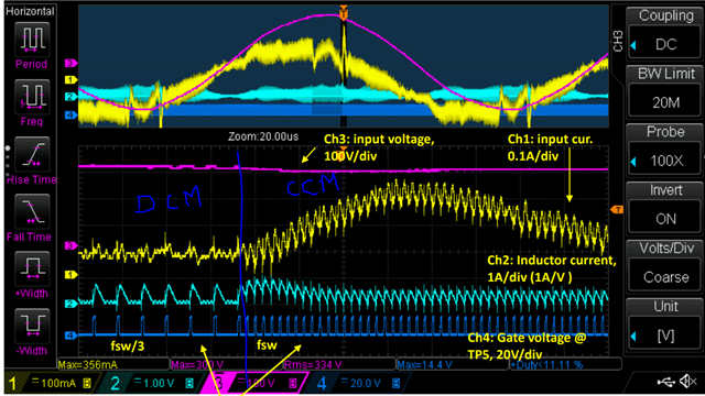
1. The converter clearly transitions into DCM mode at a certain voltage above 200Vac as shown above which probably explains the reason for switching at lower Fsw and the over shoot we see is when this comes out of this mode and controller tries to regulate/correct current immediately. What I suspect is when input voltage changes (close to peak ~200V), there is a a change in critical conductance factor (kc) which is causing the mode change. I expect the waveforms to be not good at 25w, but definitely expected better results at 60W. I am not doubting the control loop parameters for now because you are getting good regulation at 85V/max power where bandwidth would matter the most. Is it possible for you to increase the inductance say double it from the existing value to around 1.3mH and let me know your observations. I apologize for this inconvenience of burdening you with testing using a new inductor.

2. The Vff is ideally supposed to be around 4.6V at max line voltage and 1.4V at 85V. If there is any distortion here it can affect results. Can you please check if Vff is getting clamped while you increase the voltage?
3. Can you also measure the results at 120W & 200Vac and compare it with 200Vac and 60W case to see if the distortions arise at close to the same point of peak voltage? I probably suspect the distortion of current at peak might increase but just wanted to have this data point. Lastly can you check it at 220Vac and 60W.
I have been trying to work on the TINA model of UCC2818 but I am not able to replicate this issue, but will keep you informed if I am able to make any progress.
Regards,
Harish
Hi Harish,
Thank you very much for your usual support.
Hi Alex/Archie
Thank you again for the detailed analysis again.
From the waveforms we can clearly conclude there is a minimum on time limit reached, which causes this pulse dropping/frequency reduction resulting in mode change as you have clearly pointed in the conclusion slide point 6. Ideally these controllers are optimized for best performance in CCM mode. On time, ton = LI/Vin
This is probably the reason why the waveforms are better when the inductance is doubled at 120W power where the distortion starts to creep in at 250Vac but the same distortion appears much earlier at around 200Vac when the inductor is less.
At 30W, the curents are very less and I do not expect improvement in performance at higher input voltages which matches with the simulation results.
Ideally for these power levels we would recommend going with a transition mode PFC controller like UCC28064/65/56 for better performance. But I understand in your case that you might require a combo PFC/flyback for a reason. I think you will have choose the inductor, to ensure 120W performance at 85V/265V is acceptable and 30W at high line would be difficult to meet with this controller. Please let us know if you have any questions.
Regards,
Harish
Thank you, Harish.
Your guidance have been very helpful. Alex team noted, that they will increase the inductance, maintain the other changes as you recommended and repeat the test at various loads and input voltages.
Hi Alex/Archie,
Thank you for your constant feedback and testing. It really helped. Please feel free to post your report here or through private email. We can review them and close this.
Regards,
Harish