This thread has been locked.

If you have a related question, please click the "Ask a related question" button in the top right corner. The newly created question will be automatically linked to this question.

LM5085: Frequency above frequency calculated.

Part Number: LM5085

Hi Daniel Li14 & Hongjia-Wu.

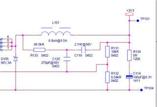
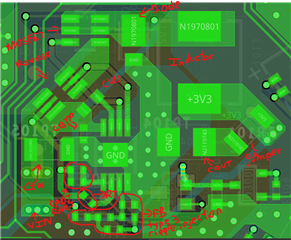
In the new design we are using the type-3 ripple injection way and we did the changes in layout to reduce the loops and system is working fine, working with load (1 A) and no load at 13.5V as input.

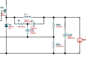
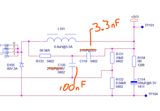
Attached the schematic and new layout we are using.

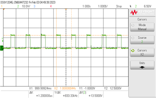
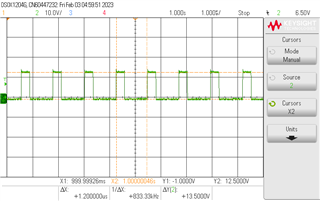
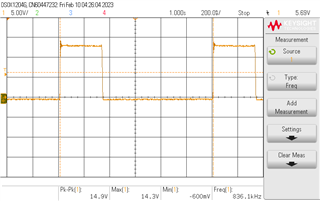
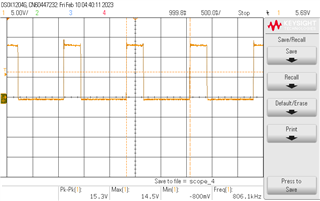
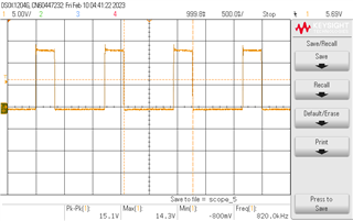
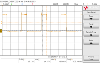
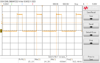
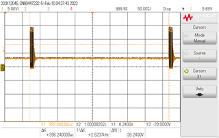
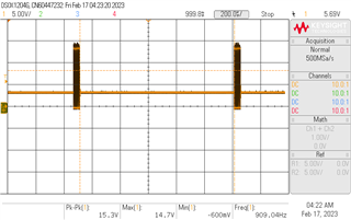
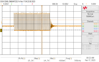
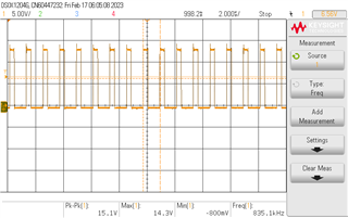
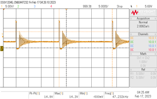
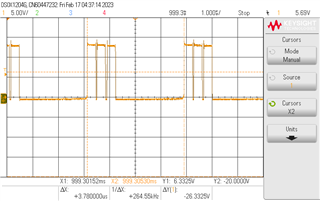
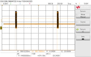
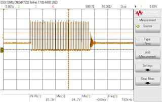
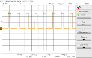
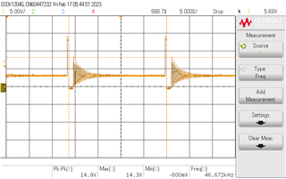
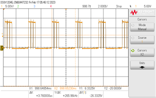
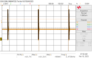
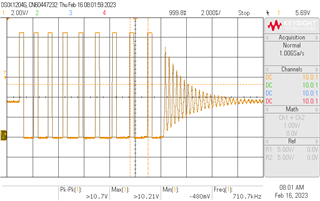
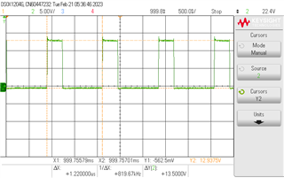
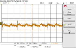
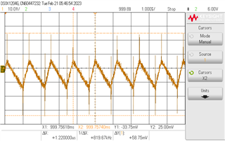
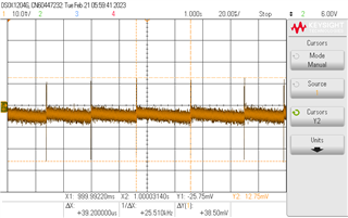
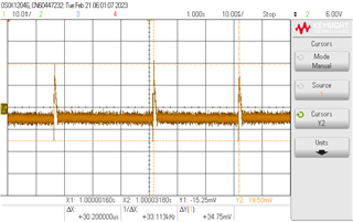
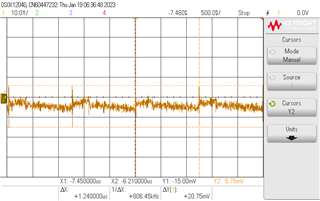
The only questions I have now is about frequency, the frequency calculated with RT = 21 Kohms (1% tolerance) and tD = 64.8 ns (50 ns + 14.8 ns) is around 726 KHz but we are measuring around 806 KHz (image attached).

We are using the MOSFET CPH6355. I understand due to resistor tolerance (RT) & turn on & turn off delay times (typical or maximum), frequency can change a little bit, but I am making calculus and I don't get more than 760 KHz.

So, what can be affecting the frequency? and this difference between frequency measured and frequency calculated, can be considered as the DC-DC converter is not working properly?

If you need more information, more graphs please let me know.

Thanks, and regards.

  • Hi,

    Can you load the device with some amount of current (500mA -1A) and check the switching waveform? I want to make sure it is in continuous conduction mode (CCM) to see a stable switching waveform.

    Also the waveform you provided looks a bit choppy, as I would expect the switching waveform to be square shaped. Where are you probing at and can you probe right at the exposed primary terminal of the power inductor?

    Regards.

    Jimmy

  • Hi Jimmy.

    Sorry for the confusion. Waveform I uploaded previously was of VOUT not VSW.

    Attached are the VSW with a load of 1 A.

    And VSW with a load of 650 mA. Same frequency.

    Also, I tested at 850 mA, 750 mA & 700 mA and the form and frequency is the same.

  • Hi,

    Apologies I missed this reply from you. 

    This looks to be consistently switching at 833kHz at the CCM condition. It's good to know that it is operational and regulating. 

    I have confirmed that based on the equation, the expected switching frequency should have been closer to 726kHz. 

    I was wondering if you can try another device to see what the switching frequency is to see if there might be any part to part variation here.

    Regards,

    Jimmy 

  • Hi Jimmy.

    Tomorrow or this Friday I will send the results, please keep this post open.

    Thanks.

  • Definitely. I will wait for further feedback from your end.

  • Hi Jimmy.

    Attached the VSW of other 3 board with load.

    Board 1 at 650 mA (left graph) and 1 A (right graph).

    Board 2 at 650 mA (left graph) and 1 A (right graph).

    Board 3 at 650 mA (left graph) and 1 A (right graph).

    All boards at 650 mA and 1 A are above 800 kHz. It seems all boards are working similar. What is your opinion about this?

    And also, a second question related to performance at light loads or no load. We are seeing the same behavior that is posted in link attached:

     LM5085: Encountering multiple pulses in discontinuous conduction mode - Power management forum - Power management - TI E2E support forums.

    Following image is what we are seeing with no load (current in uA).

    In that post is mentioned that the behavior "has probably to do with the noise floor at the FB pin and the trace length / routing of the FB network and the ripple injection components". So, this behavior can affect converter performance? if yes, what did you recommend?

    Thanks, and regards.

  • Hi,

    Thank you for the detailed graphs of the SW behavior. 

    Let me review the curves and check with the internal team on why this frequency is slightly different than equation.

    Regards,

    Jimmy

  • One thing I would suggest is to take the LM5085EVM and configure it with the exact same components shown in your schematic to check operation. It may be a board layout that could be causing the multiple pulsing at noload / DCM condition. The EVM layout would be the preferred layout and the expected SW node should look like a single square wave pulse with some DCM ringing due to parasitic resonance on the catch diode. 

  • Hi Jimmy.

    I will test that about DCM. 

    And about frequency in CCM, let me know when your team can check it.

    Thanks, and regards.

  • Hi,

    Thanks for the update. I will wait for more details on your testing of your components on the EVM.

    I am also trying to get in contact with the team to go over the equation in CCM and will get back to you with more details on it soon.

  • Hi Jimmy. 

    We could not test the EVM with our components, at least for now is not possible for us but we do the following using as reference LM(2)5085_QuickStart.

    Starting from we are seeing the following in DCM with our current implementation.

    1. Selecting Typer 3 for the ripple injection circuit from LM(2)5085_QuickStart, we have different values compared to the values of TI Webench.

    So, we changed the following components:

    The result was a similar behavior in DCM, but with more pulses where it seems is working as CCM during DCM.

    In CCM is still working well (1 A load)

    2. Selecting type 2 for the ripple injection circuit from LM(2)5085_QuickStart, we did the following changes:

    With this in DCM mode is working well, only one pulse.

    But with load is not regulating properly, similar behavior that we have in the first post we did LM5085: Output voltage issue. - Power management forum - Power management - TI E2E support forums

    Taking into account comments for the first post we did and also recommendations from the LM(2)5085_QuickStart about the Rsense to have 50 mV across it at maximum load current, for point 1 and point 3 we are changing Rsense from 10 mOhms to 30 mOhms, and Radj from 1.07 Kohms to 2.7 Kohms.

    3. Point 1 with Rsense = 30 mohms, Radj = 2.7 Kohms.

    We are still seeing same behavior as point 1.

    In CCM is still working well (1 A load)

    3. Point 2 with Rsense = 30 mohms, Radj = 2.7 Kohms.

    As in point 2 in DCM we are seeing only one pulse.

    But in CCM is not regulating properly.

    So,

    with a type 2 ripple injection circuit we have only one pulse in DCM but is not regulating properly in CCM.

    with a type 3 is regulating well in CCM but with light load or no load it seems we have the switching of CCM inside a DCM state and considering the number of pulses of CCM during DCM, best case for now is the board with type 3 ripple injection circuit without modifications.

    I hope this can help to understand what is happening.

    Thanks, and regards.

  • These new images are not the same images that I saw at the beginning of this post where you were only concerned with the switching frequency at CCM.

    For my own understanding, what changed between then and now? Before at CCM, the SW looked stable and square shaped, albeit it was switching at around 833kHz instead of the calculated 726kHz follow datasheet equation. What configuration was this in?

    Now I see SW waveform for Type 2 an Type 3 ripple injection. Can you attach the LM5085 design calculator tool with your filled out information for review?

    For a 12Vin|3.3Vout|730kHz operating at 1A, I suspect your inductor is too low.  

    Regards,

    Jimmy

  • Hi Jimmy.

    Yes, initially I was only concerned about the switching frequency at CCM but then checking the DCM we saw that we have several pulses instead only one.

    With the following Type 3 ripple injection in next image, we are having in CCM a VSW stable and square shaped as you said, but with frequency at around 833 KHz instead 726 KHz (our first concern)

    But in DCM we are having this:

    As you can see, several pulses instead only one, it seems it is a CCM inside a DCM mode.

    So, in two in our boards we did modifications in the components, one board keeping type 3 ripple injection but changing the value of the components and in a second board changing to a type 2 ripple injection.

    Results as you can see in previous comments was that changing the components of the type 3 ripple injection, increased the pulses in DCM mode (CCM still working well) and using type 2 ripple injection we have only one pulse in DCM mode but CCM is not working properly.

    Attached is the calculator with our values.

    0564.LM(2)5085_Quick_Start.xls

    The values of the type 3 ripple injection that the excel calculator recommends are different from the values in TI webench.

    And about the inductor, the inductor we are using is IHLP2525CZER6R8M11, 6.8 uH.

    In TI webench we have as option select that inductor but in the excel calculator is recommended an inductor greater than 9.1 uH to reduce the ripple current.

    I appreciate your comments.

  • Hi Jimmy.

    I did the following changes in type 3 ripple injection (C119, from 2.7 nF to 3.3 nF & C120 from 270 pF to 100 nF) and DCM and CCM is working properly (CCM still above 800 KHz, not 726 kHz but regulating properly), but I have some questions at the end of this reply.

    With the changes mentioned I have the following:

    At 13.5V

    in CCM mode (1 A load), VSW (green) & VOUT ripple (yellow) 

    VFB ripple

    in DCM (less than 10 mA as load, frequency between each pulse can vary a little bit here because current is changing between uA range to less than 10 mA), VSW (both green below)

    VOUT ripple

    VFB ripple

    So, two questions:

    1. I still have the question about why we are having above 800 KHz instead 726 KHz in CCM mode? could you check this?

    2. For R133 (part of the type 3 ripple injection), in the LM(2)5085 calculator that I attached in a previous comment is indicated that should be less than 15.8 Kohms, and doing calculations indicated in datasheet I am obtaining around 20 Kohms (with 4.5V as minimum input voltage), but placing in R133 a resistor of 15Kohms or 20 Kohms (with C119 = 3.3 nF & C120 = 100 nF) is not helping, I having something like this in DCM mode.

    Only until increase the R133 (I tried with 43 Kohms, 66.5 Kohms & 75 Kohms) I can have a proper performance as you can see in the first graphs of this reply.

    So, I wanna understand why I had to increase the resistor if the calculations indicate that it should be a resistance of lower value, could you help to understand this?

    Thanks and regards.

  • Hi,

    It's good to heard that you were able to get the expected waveform at both DCM and CCM with the type 3 ripple injection changes.

    1. I've asked around but didn't get anything different from what we are expecting. The LM5085 is a relatively older part (2008 - 2015) so the team members have long since moved on. Without much reference other than the datasheet, I would have to defer to the RT equation unfortunately. On my end, I put the RT and ripple injection calculation in an excel spreadsheet and also arrived at the same calculation results as you did. LM5085 E2E Equations.xlsx

    2. My thought here is that the equations are valid for CCM application. Note that the in the datasheet section for ripple injection calculation "A minimum of 25 mVp-p must be applied to the FB pin to obtain stable constant frequency operation". Therefore it is assumed that the values here should be applicable for CCM condition so you should expect a fixed/stable and constant frequency when loaded. However if you are operating at DCM, then your frequency will shift and change since device is operating in light load and switching frequency would scale back. In discontinuous conduction mode, where the inductor’s current reaches zero during the off-time, the operating frequency is lower than in continuous conduction mode and varies with load current. This pulsing of the SW at DCM may be an expectation of the component configuration if you were to follow datasheet recommendations

    Regards,

    Jimmy  

  • Hi Jimmy.

    Thanks for all your comments and comments of TI team, that helped to have the DC-DC converter regulating properly in CCM & DCM mode.

    I hope not having more issues with this.

    Thanks, and regards. 

  • Hi,

    Thank you for using the E2E forum.

    Regards,

    Jimmy