This thread has been locked.

If you have a related question, please click the "Ask a related question" button in the top right corner. The newly created question will be automatically linked to this question.

TPS2546: Datasheet Question: Table 3 - Mode Selection

Part Number: TPS2546

Hello,

I am looking to use this product (TPS2546RTER) in my USB-A charging design. I am not transferring any data and just doing charging (aka DCP). 

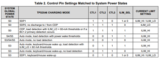
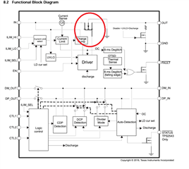
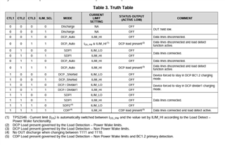
I am looking to charge up to 12W with a status to activate the current limit (0.2A - 2.97A, approximately). So I have the current configuration:

CTL1 = 0

CTL2 = 1

CTL3 = 1

ILIM_SEL = 1

ILIM_LO Resistor: 210kOhm

ILIM_HI Resistor: 16.9kOhm

According to the data sheet, this configuration seems right, but the note confuses me. "DCP Load present governed by Load Detection - Non Power wake limits."

Does this mean that it will be INACTIVE between my current range (0.2 - 2.97A)? If not, what would be the result?

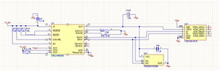
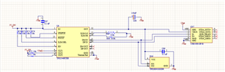
As a reference to ensure the design is correct, please see my schematic for it below

  • Hi Kyle,

    Load detection means the device needs to reach the set threshold associated to the power state mode you are in. Therefore in your configuration, you will need to draw enough current to pass load detection without power wake limits. This information can be found in Table 2:

    Therefore, it will be inactive from 0-(ILIM_LO+60mA) and active from (ILIM_LO+60mA)-(ILIM_HI). In your scenario you have set ILIM_LO (210kohm) = ~240mA so your minimum current you most draw in order to wake = 240mA + 60mA. Your ILIM_HI (16.9kohm) = 2.97A.

    Very Respectfully,

    Brandon Beader

  • Hello Brandon,

    Thank you for the reply. If this is the case, I don't see the difference between 001 and 011 in this case, aside from the additional 60mA buffer on the 011 ILIM_LO. I see the keyboard/mouse wakeup, but I don't see how that's relevant to charging (unless I'm misunderstanding). 

    Is there any difference if I'm just using this port for charging?

  • Hi Kyle, 

    The difference falls in the charging state you are in. For 011 you introduce wake on USB mode. More details on this feature can be found in the data sheet but the high level understanding is the D+/D- must stay connected to USB host in order to wake from USB data. The setting for 001 is auto mode which is similar to 011, except it does not support wake on USB.

    Very Respectfully,

    Brandon Beader

  • Hello Brandon,

    Thank you for the clarification. So in essence:

    001 - Only wakes up if it's within the power range defined on the ILIM resistors

    011 - Wakes up if it's within the power range defined on the ILIM resistors OR if the USB wakes it up

    Is this correct?

  • Hi Kyle,

    Yes, you are correct. I recommend reading section 8.3.4.3 in TPS2546 Datasheet. It explains the USB wake function. 

    Very Respectfully,

    Brandon Beader

  • Hello Brandon,

    Thank you for confirming this. I believe this all makes sense now! My question is answered.

    My only follow-up question lies now in how the device reacts to a USB connecting to the port and this device trying to charge it. There is a MOSFET between the power IN and OUT, which of course is controlled to regulate the current.

    So initially when a device is plugged in, it will start trying to charge, but the TI device is inactive until the ILIM_LO + 60mA is achieved. If the device is inactive, is the device still switching? If that's the case, then the ILIM_LO does not prevent a device trying to charge below ILIM_LO + 60mA, but the status flag would remain inactive. 
    If a load that exceeds the ILIM_LO + 60mA appears, then the status flag will go active.

    Is this logic correct?

  • Hi Kyle, 

    Can you calrify your question? When you say USB is connect to the port and device is trying to charge it, are you refering to when we have USB host connected to D+/D- lines as well as BC1.2?

    Which MOSFET are you refering to? Do you have a block diagram or a schematic?

    Very Respectfully,

    Brandon Beader

  • Hello Brandon,

    I am still learning the USB terminology, so I apologize if I mess any of them up, but I am referring to the external load that the TPS2546 is charging (i.e. a phone, a laptop, etc.). My goal for this design is to charge these devices, up to a maximum of 12W. 

    When an external load is connected to the USB-A connector (CN7 in this picture), the TPS2546 is supposed to detect a load. 

    The TPS2546 detects the load based on the current settings (in my case, the ILIM_LO + 60mA, which is about 300mA). When that is detected, the device is supposed to set the status to active low. However, there is an internal MOSFET to the TPS2546 that is part of the power path. See the picture below.

    If this MOSFET is open, then there is an open circuit in the power path. If that's the case, the 300mA can't be achieved because there's no path for current to flow. This is where my confusion lies. 

    Is load detection merely a signal change on the STATUS pin? In other words, that MOSFET is always switching and providing power to any load, but the device will only send a STATUS active-low signal to any monitoring devices (i.e. the MCU, a status LED, etc.) when the current is above ILIM_LO + 60mA. Is this correct?

  • Hi Kyle,

    Brandon is currently out of office and will be back by Tuesday.

    Thanks and Regards,

    Chris

  • Hi Kyle, 

    Yes, you are correct. The internal FET will always be switching in order to provide power. The CTL pins and ILIM_SEL are merely used to set the charging mode the device will operate as well as the current limit setting. 

    The STATUS pin is used to implement features such as power management or power wake. This status pin is open-drain, active low. For example, in power wake mode the status pin can be used to switch between the high power DCDC converter and a low power LDO when in sleep mode or operating mode. 

    Very Respectfully,

    Brandon Beader