This thread has been locked.
If you have a related question, please click the "Ask a related question" button in the top right corner. The newly created question will be automatically linked to this question.
Hi TI expert,
I am looking for a simple solution on LLC Converter,
and I find the UCC24610.
I have a question about this example circuit.
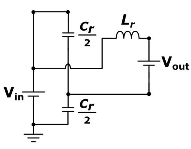
on the page 8, what are the function of these two capacitor? are they resonant capacitor?
if yes, why they are not in the series? I also study this document. the datasheet only said the C5 and C6 are for load current.
May I know how does this function work? why they can parallel each other. how to analyze it.
thanks in advacne.
Hi Jack,
Thanks for reaching out to us.
From the fundamental harmonic analysis, effective resonant capacitance is C5+C6 (parallel combination of C5 and C6. Here resonant inductor current is split between these capacitors).
Splitting these resonant capacitors have several advantages compared to using single resonant capacitor.
Please go through 6,7,28,29,30 of the following app note for details:
Please let me know if you have any further questions.
Regards
Manikanta P
Hi Pallantla,
Thanks for your information.
I have one question, these two capacitors are not in parallel, why the resonant frequency is the same as the series capacitor?
Jack
Hi Jack,
As I mentioned before, though upper resonant cap connected to DC bus, from the fundamental harmonic analysis, upper resonant cap is still connected to gnd (Here input voltage is considered as pure DC voltage) which means both the resonant caps are connected in parallel. So, effective capacitance value is same as single resonant cap value.
I would recommend building a open loop LLC simulation and check the frequency of current yourself by using different resonant cap configurations.
Regards
Manikanta P
Hi Pallantla,
Yes, I do the simulation, and the parallel capacitor's resonant frequency is the same as a series capacitor.
I am confused about one thing, I know the input voltage is a pure DC voltage. but why we can ignore the DC voltage and think the upper side capacitor is parallel with the low side capacitor?
Maybe this is a stupid question, I am sorry about that.
Jack
Hi Jack,
I am saying when you analyze the power stage in frequency domain, the DC input voltage can be considered as short and swith node volatge is considered as AC voltage source. But in time domain, you should not consider that way.
Regards
Manikanta P
Hi Jack,
Let me give you different perspective here.
Assume that converter operates at the resonant frequency.
When the upper switch on the primary side is on, the effective circuit would be as below. here switch node voltage is equal to Vin.
On secondary side, assume upper diode is conducting. So effective circuit will be as shown below. here magnetizing inductance will be clamped by the output voltage.
To see the effective resonant circuit, short the DC voltage sources.
Now you can clearly see that, Lr resonantes with the combinantion of Cr/2.
Hope this clarifies.
Regards
Manikanta P