This thread has been locked.

If you have a related question, please click the "Ask a related question" button in the top right corner. The newly created question will be automatically linked to this question.

TPIC71004-Q1: Unexpected behaviour while short to GND

Part Number: TPIC71004-Q1

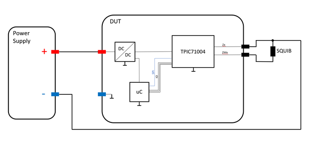
The DUT has volage supply but is without ground connection. The uC on the DUT is not flashed with software. Now we are applying a short to GND at the Zx pin of the TPIC71004. The voltage of the plane is at 1.6 V higher compared to minus of power supply (I know that we are out of the range of the absolute maximum ratings of the Zx pin). A current is flowing in to the Zx pin (about 25 mA). And there is a voltage difference between Zx and ZMx pin. Do you have any suggestions to avoid this?
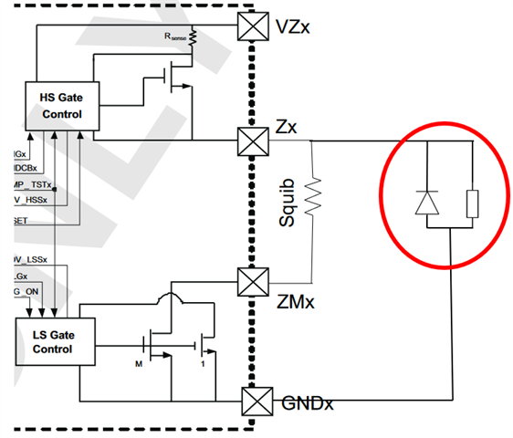
I have red the NOTE “
Applying a negative voltage on the Zx pins will cause current flow through the squib via the body diode of the low side switch even if the low side switch is commanded OFF. This can lead to inadvertent deployment (firing).“ Is there any possibility with external components around this behaviour.

  • Do you mean GND plane is 1.6V higher ?

    Norikazu

  • Yes, the GND plane of the DUT is 1.6 V higher than the minus pole of the Power Supply and the Zx Pin of the TPIC 71004.

    I am very interested in how it is possible to protect the Squib against the mentioned note.

  • As you commented, applying a negative voltage on the Zx pins will cause current flow through the squib via
    the body diode of the low side switch even if the low side switch is commanded OFF. This can lead to inadvertent deployment (firing).

    You need to avoid negative voltage. Clamp circuit on Zx pins would reduce a risk of negative voltage but it depends on the power supply- capability.

    Norikazu

  • You are saying that we should place a clamping circuit on Zx pins but although talking about power supply capability. So where would you recommend placing the clamp circuit?

    The problem is that the squibs are firing in our test case described bevor. This test is part of the LV124 E17. So your device is automotive qualified, how have you passed this test?

  • The test you are trying to do is "Short to GND", however, in your setup, it is not short to Gnd but pulling the pin to negative voltage and violating absolute maximum rating. Can you change the test setup to make the test condition to "short to Gnd, not negative voltage" ?

    Adding clamp circuit to Zx pin would help pin voltage to stay at GND level but it may be better to update the test setup to do 'short to Gnd' test. 

    Norikazu

  • It is not possible to change the test setup shown in the block diagram. The test must be performed without GND connection of the DUT, and the outputs must be connected to GND (minus of the power supply). Due to pullups and other body diodes of components which aren’t shown in the block diagram, the GND plane of the DUT isn’t a 0V.

    Do you want me to connect the clamping circuit like this?

    In this case the clamping circuit will not save our problem, because we than still have the problem, that current is flowing trough our squib. Additionally, the voltage at the Zx pin is still not 0 in comparison to GND because of the Vf of the Diode.

  • The current goes through FET body diode, external diode may not help.

    Can you email me (ntake@ti.com) for off-line discussion because the condition is out of specification ?

    Norikazu