This thread has been locked.

If you have a related question, please click the "Ask a related question" button in the top right corner. The newly created question will be automatically linked to this question.

LM5155-Q1: about LM5155 used in boost mode

Part Number: LM5155-Q1
Other Parts Discussed in Thread: LM5155

Hi team,

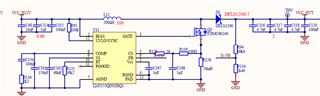
   Pls look at the schematic:12V input,output configuration is 70V,and the load consumption current is 140mA.

  I want to improve the efficiency of the system, so I change the R135 resistance value to 48.7K. Other conditions remain unchanged, but the total current of the system has a loop jump. I guess it is because the output current of this part of the power supply is not enough. It is assumed that the smaller the fsw is, the larger the output current should be under the condition that other conditions remain unchanged. However, the opposite result appears.

  • Hello Suy,

    Thanks for reaching out to us via e2e.

    The change of the frequency from 550 kHz (39K2) to 445 kHz (48K7) would not make much of a difference (but also it would not change the efficiency a lot), if your converter was calculated properly.

    The problem with your design is that the components have not been chosen in the right way and especially the components of the compensation network are way off the reasonable values.
    Therefore, there is not enough phase-margin and the converter is instable.

    Please download the LM5155/56 Boost Controller Quick Start Calculator which you can find here: www.ti.com/.../snvc224
    This tool will help you to calculate the components of your converter in the correct way.

    Here are my major findings:

    Output voltage
    The shown values for the voltage divider (R94=86K6 R134=2K49) would result in an output voltage of 36V
    If you want to reach 70V, these values must be different.

    Inductor
    for 36V a value of 30uH would be recommended, for 70V this would be around 16uH.
    Your design is using 200uH instead. (Nevertheless it can still work.)
    Please make sure that there is enough margin between input current and the satturration current of the inductor.
    Also, most inductors are de-rating and/or running hot at higher frequencies.

    Compensation network
    This is the most critical part that makes your system instable!
    Recommended values would be:
    R136 = 22K, C134 = 17nF, C161 = 800pF (0.8nF)  !

    The Quick Start Calculator tool also shows you that there will be lower losses in FET and diode with the lower switching frequency.

    Best regards,
    Harry

  • Hi harry,

        Thanks for your detailed answer and pointing out errors in the schematic.

        Another question,i found two parameter of the gain and phase in the bode plot,how can i choose the value of gain and phase in the system?

  • Hello Suy,

    There is no single parameter that you could change to influence either gain or phase margin.

    These parameters not only depend on the components of the compensation network, but also on the chosen components of the power stage, supply- and load conditions, etc.

    Because the dependencies are complex, we are offering the quick start calculator to help you with the choice of the components of the compensation network.

    You should reach a phase margin of 60 degree and a gain margin of 20 dB.

    For further information please have a look at this document:

    Switch-mode power converter compensatin made easy

    Best regards,

    Harry

  • Hi harry,

      I read the article you recommended, but I found on page 4 of the article that the gain margin had better be -6db, which is quite different from the 20db you mentioned. Is it your mistake?

    By the way, what is the definition of -6dB, which is not mentioned in the article.

    The article describes it as follows:

    "Sufficient phase margin is required to prevent oscillations. A phase margin of 45 degrees or greater is the design goal. A gain margin of –6 dB is the minimum, while –10 dB is considered good"

  • Hello Suy,

    I have sent the article because the topic is too complex to explain all details on this forum.

    Regarding the limits, it is very simple: The more margin you add, the bigger is the chance that the system will work stable under all worst-case conditions (across temperature / tolerances / aging of components, etc.).

    We usually recommend a phase margin of 60 degree and a gain margin of 20 dB.

    As per the quick start calculator, this is possible with the components that I have recommended:
    R136 = 22K, C134 = 17nF, C161 = 800pF (0.8nF) 

    Best regards,

    Harry

  • Ok,i got it,thanks a lot.