This thread has been locked.

If you have a related question, please click the "Ask a related question" button in the top right corner. The newly created question will be automatically linked to this question.

UCC27211: UVLO function simulation about UCC27211

Part Number: UCC27211
Other Parts Discussed in Thread: TINA-TI,

Hi team,

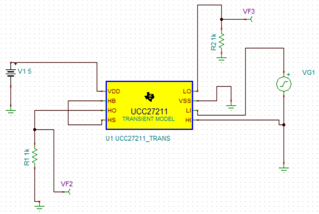
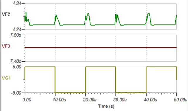
I simulated the UCC27211 through TINA-TI and I connected HS and HO directly as shown below. According to datasheet, UCC27211 has the UVLO function, so I understand that the output voltage of HO should be 0. But It seems that the output voltage of HO is 4.25V with some spikes when LI is turning low to high. I wondering what is causing this phenomenon. Could you kindly help to explain the reasons?

Thanks a lot. And wish you have a nice day!

  • Hi Jerry,

    Thank you for reaching out, and I hope you have a nice day as well! Can you provide some background on the goal of the simulation?

    As you can see from the typical application setup found in the UCC27211 datasheet, the HS pin needs to be connected to the negative side of a bootstrap capacitor. This capacitor is responsible for charging and discharging the high side FET. The HO and LO pins should be directly connected to the high-side and low-side power switches, respectively. HS also needs a reference to ground to help with refreshing the bootstrap capacitor every switching cycle.

    These changes to your schematic should help the device to behave as expected. If there is a reason that you can't make these changes due to a specific use-case, please let me know.

    Best,

    Alex Weaver