Other Parts Discussed in Thread: UCC28782, , UCC28781EVM-053
This EVM states 90Vrms minimum input voltage, what happens at lower input voltage? Can this IC be used at 60V input?
This thread has been locked.
If you have a related question, please click the "Ask a related question" button in the top right corner. The newly created question will be automatically linked to this question.
This EVM states 90Vrms minimum input voltage, what happens at lower input voltage? Can this IC be used at 60V input?
Hello Valentinas,
Thank you for your interest in the UCC28782 ACF controller.
The UCC28782EVM-030 is rated for continuous full-load operation at an input voltage as low as 90Vrms.
It will also run continuously at 85Vrms, 80Vrms, and lower, but the primary side currents will increase and primary-side components will get hotter.
At some lower voltage (I'm not sure where, maybe 75Vrms?) it will trigger the "Brown-out" protection threshold and shut down.
The IC can be used at 60Vrms or 60Vdc or any other voltage higher than about 20V that you program it for (using Rvs1 and Npa turns ratio).
Input voltages lower than 20V make it difficult (or impossible) for the depletion MOSFET on the SWS pin to start the controller and to sense the switched-node signal.
Regards,
Ulrich
Hello Ulrich,
I calculate it on UCC28782EVM-030 and it seems to make sense but i do have UCC28781EVM-053 on my desk and it seems to turn on only at 100Vdc, even if Nap is 0.151, according to the user manual. However, based on the resistance which is around 20k, i would expect it to brown-in at around 48V? Please check my calculation below.


Thank you,
Valentinas
Hello Valentinas,
I agree with your math and your expectations, and in most off-line designs your expectations would be met.
However, in the case of the UCC28781EVM-053 wide-Vin design, the turn-on current threshold of 365uA at VS is not the limiting factor for power up.
There is another protection threshold that supersedes the Ivsl(run) threshold.
That protection is the CS pin-fault timer tCSF1 at 2.05us (typ).
It's function is to detect a shorted CS input at start-up and shut down further operation if it detects one.
If the controller does not detect a voltage at the CS input that exceeds the first start-mode threshold Vcst(sm1) = 0.2V (typ) within 2us of PWML going high, then the controller assumes a shorted-pin fault for CS and aborts start-up for a UVLO cycle.
With a magnetizing inductance of 160uH, the bulk voltage must exceed about 100V to avoid triggering this fault. Therefore, the EVM cannot start at bulk voltages lower than 100V. The second paragraph of Section 6.2 of the EVM User Guide mentions this, although it does not elaborate on the reason.
Once the EVM is started, continuous operation at lower voltages (down to 50Vdc) is possible provided the lower output current limit is also respected.
Regards,
Ulrich
Thank you Ulrich, now i am getting a better understanding of it.
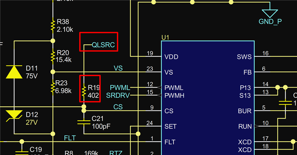
So, if QLSRC charges up the CS, can i reduce the R19 a bit to make it turn on at lower than 100V input? Or will i damage my EVM?
Hello Valentinas,
Unfortunately no, that's not how it works. Reducing the value of R19 will not allow the EVM to start up at voltages lower than 100V.
Reducing R19 value only increases the peak primary current allowed at high input voltage which would tend to overheat the transformer.
The start-up voltage of this EVM cannot be reduced without also significantly reducing its maximum output power.
Remember that avoiding the CS pin fault requires the Vcs rise to 0.2V within 2us of PWML rising edge. Those two parameters are fixed.
Vcs comes from the primary current building a voltage across the current sense resistors R21 and R28 (which is then transmitted through R19 to the CS input).
The calculation is a simple V/L = di/dt manipulation. For a 50-V start threshold: 50V/160uH = di/2us, and so di = 0.625A.
The 0.625A peak would correspond to 0.2V if the sense resistance = 0.32 ohms, about double the resistance currently on the board.
Changing the values of R21 and R28 to result in 0.32R would effectively cut the power capability of the EVM in half.
The only other means would be to redesign the transformer for an inductance of 80uH, but this would also have undesirable side-effects which I don't want to get into.
I strongly recommend against making any changes to the EVM without first having a thorough understanding of each function of the controller and the reason for the component values chosen to support those functions, AND the potential consequences of making any changes to any of the components.
Regards,
Ulrich