This thread has been locked.

If you have a related question, please click the "Ask a related question" button in the top right corner. The newly created question will be automatically linked to this question.

REF5020: Choosing capacitors for REF5020

Part Number: REF5020

Hi Sir,

I am a bit confused about choosing capacitors for a very stable voltage reference using REF5020.

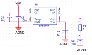
Let's look at the following figure

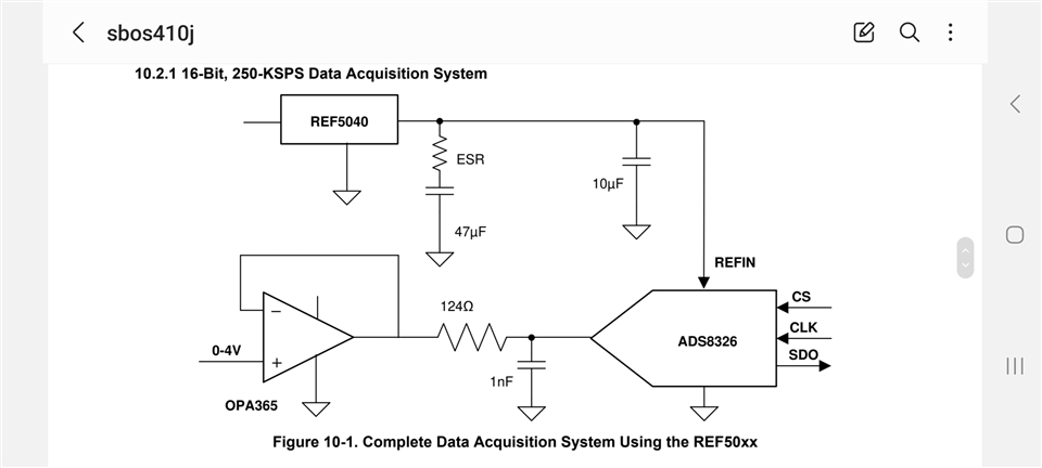
As what I read in the REF50XX datasheet, the output capacitor (the 47uF capacitor in the Fig.10.1) must be a low ESR one, and the total resistor value in series with this capacitor should be from 1Ohm to 1.5Ohm.

There are some more capacitors in the circuit, so is there any similar requirements with those capacitors (the input capacitor at Vin pin, the 10uF ouput capacitor and the 1uF capacitor at the TRIM/NR pin)?

I think the best choice for the 47uF output capacitor is an ultra low ESR tantalum capacitor in series with a 1Ohm resistor. But I am not sure about the others. Am I right?

And can I connect some .1uF NPO capacitors in parallel with the output for getting rid of high frequency spikes?

I am looking for your help.

Thank you and best regards,

Tuan Tran.

  • Hi Tuan 

    Please follow the recommendation given in layout guideline in section 12 (page21) in the data sheet. ESR for output capacitor should be upto 1.5 ohms. You can choose an ultra low ESR cap with 1 ohm resistor in seriese, that will suffice the requirement.  You should put ultra low leaakage capacitor on the NR pin capacitor. Any leakage at NR pin capacitor will cause output shift. 

    Input capacitor is supply decap which will stablize the supply against any transient / noise. You can choose any capacitor at the input depnding on your supply noise and stability requirement. 

    Regards

    Trailokya 

  • Hi Trailoky,

    The last sentence in section 12.1 says that a 1uF high frequency capacitor can be added in parallel with the output pin and ground, and I am not sure if it's possible if I put a Tantalum capacitor with an ESR of about 4or 5Ohm at this output, or I should choose an untra low ESR capacitor in series with 1Ohm resistor?

    I am sorry because I am still a bit misunderstanding and hope you can explain me more.

    Best regards,

    Tuan Tran

  • Hi Tran 

    The ESR requirement is 1 ohm to 1.5 ohm . Please choose ultra low ESR cap with 1 ohm resistor in seriese. 

    Regards

    Trailokya 

  • Hi Tran 

    Please let me know if you have any query? 

    Regards

    Trailokya 

  • Hi Trailoky,

    Thank you for your help.
    I am going to update my design with your information.

    Regards

  • Hi Trailokya Rai,

    I have just assembled the below circuit

    The input voltage (VDD) is a stable +5V

    C5 is a tantalum capacitor

    C6 is an MLCC NP0 capacitor

    C8 is an ultra low ESR Tantalum capacitor

    There is no C7 installed because I have not bought any low leakage capacitor as your suggestion

    The PCB layout is similar to the figure 12.1 in the datasheet

    and the output current is close to 0mA (very small, I guess)

    Every thing seems to be OK but the output voltage is only 1850mV instead of 2048mV as it should be and very stable as I watch it by the oscilloscope.

    Did I do something wrong?

    Hope you can help me to solve this issue.

    Thank you and best regards, 

    Tuan Tran

  • Hi Tuan 

    It looks good to me. You can use tantalum or polymer capacitor for C7.  Good luck with your design. 

    Regards 

    Trailokya 

  • Hi Trailokya,

    Is the output voltage of 1850mV is normal? In my mind, it should be 2048mV+/-15mV?

  • Hi Tran tun

    The output should be close to 2.048V.  Can you check the output on the oscilloscope and see if it is oscillating ?

    Regards

    Trailokya 

  • Hi Trailokya,

    The output voltage of the REF5020 is very stable without any spikes when watching on the oscilloscope.
    In the last circuit I made 2 weeks ago, the output voltage of the REF5020 was only 1970mV and clean and I thought that the reason was the high DCL tantalum capacitor connected at pin Trim/NR. So in this circuit I leave this pin unconnected but the output voltage still low.

    I measured the output voltage by FLUKE 179 DMM and TBS1202C Tektronix Oscilloscope.

    I include here the picture of the REF5020 I bought from a Chinese supplier.

    Regards,

    Tuan Tran

  • Hi Tuan 

    The schematic looks okay to me . Unstable ESR may cause oscillations in the output which can shift the DC measurement.  You are seeing clean output  which means the output cap is stable. 

    There should not be any drop if you leave the NR/Trim pin floating. 

    Regards

    Trailokya