This thread has been locked.

If you have a related question, please click the "Ask a related question" button in the top right corner. The newly created question will be automatically linked to this question.

UCC28065: Interleave Phasing?

Part Number: UCC28065

Hello, I am using the UCC28065 in a 115VAC, 730W PFC application.  I have noticed something curious about the phase interleave.

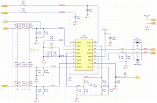
The application circuit is generally similar to the eval board, with smaller inductors to operate at higher power and frequency.  See below:

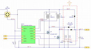
VDD is 13V. In the present test, Q1 and Q2 are SIHA105N60EF-GE3.  The drain waveforms (PFSW1, PFSW2) look like so:

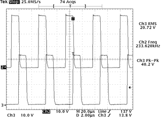
(Note: using 10x probes.) As you can see, the phase interleave is not 180 degrees. The inductors were measured and match within 5% of each other.  Please advise.

  • Hi Tim,

    It appears you've hit a limit with the PLL inside the IC. Was the waveform you included taken at no load or is it under load?  If it's no load, please put it under 50% and 100% load to see if there's a difference in the interleaving. Also, where along the input waveform was this taken?

    Also, please fill out the calculator tool so I can align with your design intentions: https://www.ti.com/lit/zip/sluc697

    Thank you,

    Ray

  • Waveform is at 730W, out of ~800W nominal design capacity. Near the mains peak.  I have seen different phase shifts near the root or middle of the line waveform as well.  Afraid I don't have enough oscilloscope resolution to show many at once.

    Values are as shown. Note interleave and burst mode thresholds haven't been optimized yet.

    UCC28065Calculator_password.xlsx

  • Hi Tim,

    Note that your transformer turns ratio is 8:1 while the tool recommends 5:1 to satisfy eq (24) in the datasheet. This will ensure the zero-crossing detector will reset at high line. Since you aren't running at high line right now, this probably isn't the issue right now. I did notice that your RZA/B resistors are lower than suggested which will expose the ZCDx clamps to potentially damaging current. These resistors are also part of an RC delay with the cap to GND on these pins. Any mismatch in the ZCD signal can result in a phase mismatch.

    These are my recommended steps at this point:

    1. Increase R32/R33 to 20kΩ

    2. Ensure C51/C52 are within tolerance

    3. Replace the UCC28065 IC (in case the ZCD clamps have been damaged)

    4. Probe both ZCDx along with GDx pins while the interleaving issue is present and non-present.

    I look forward to seeing your results.

    Ray

  • I notice the transformer ratio calculation is extremely sensitive to Vout. The resistor values used give closer to 392V which calculates a 8:1 ratio, so that should be fine.

    I changed C51 and C52 to 10pF, and R32 and R33 to 20k. Waveforms look good at a glance. Thanks.