This thread has been locked.

If you have a related question, please click the "Ask a related question" button in the top right corner. The newly created question will be automatically linked to this question.

TPS65185: pwr_good signal sometimes goes to 0

Part Number: TPS65185

Hi,

I' am using the TPS65185 to supply the Eink display (whose specification is in accordance with the PMIC specification). We use an Epson S1D13524 connected by I2C to your PMIC to drive the display.

When we are issuing the "black/white" command (to clean the display), sometimes (randomly, but rarely) it fails and the pwr_good signal goes to 0.

In this case, register value for INT1 is 0x00 and INT2 is 0xC0 or 0xC8. We are looking for what is wrong in our design and we need some clues. We are not sure if the issue is from the input power supply or the PMIC (3V8 in our case) or if it is from the elink display which need important inrush current (so the pmic can not supply enough).

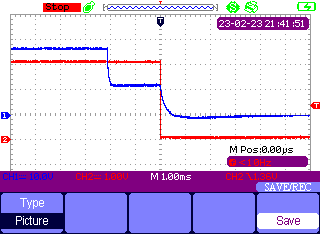
I have performed measures and as you can see on the picture below, we found one of the reason why the pwr_good signal goes to 0. The blue trace is VDDH (+26.4V) and the red trace is the pwr_good signal. It seems that the eLink display needs a rush current for a short time (So VDDH goes below 90% of its nominal output voltage and the pwr_good goes to 0)...

- What is the delay between the fault detection and the pwr_good assertion ? In our case it seems to be about 2ms (see the picture below).

- In the datasheet there is a "power good timeout" parameter set to 50ms. Does it mean that if the undervoltage lasts less than 50ms, the pwr_good signal stays at 1 ?

- Last question, if for example there is an undervoltage on VDDH_IN (pin 37), is pwr_good signal asserted to 0 ?

Thank you for your help

Best regards, Pascal

  • Hi Pascal,

     From register value INT2=0xC0, the "Undervoltage on VDDH charge pump detected";  INT2=0xC8 means both  "Undervoltage on VDDH charge pump detected" and "Undervoltage on VEE charge pump detected".

      Undervoltage (UV) on VDDH_IN (pin 37) doesn't directly cause pwr_good signal asserted to 0; but it can cause both VDDH and/or VEE UV, and then cause pwr_good signal asserted to 0. 

      The "power good time-out" parameter set to 50ms is for reading the register "Power Good Status (PG) Register (address = 0x0Fh)". 

    Thanks!

    Phil


  • Thank you Phil for you feedback,

    just another information to help us to understand the PMIC behaviour and what happens on our board.

    As you can see on the picture, the VDDH voltage decreases to about 10V for 2ms. According to the elink datasheet, the inrush current lasts 10us max. So I expect that the VDDH voltage goes back to 26V after about 10us. But it does not. So there is 2 reasons for this : the PMIC shall supply an important current for more than 10us, or the PMIC is in an "unstable" state for 2ms, even if the output current to the display becomes "normal" .

    Do you think the PMIC can stay in this state (VDDH voltage to 10V for 2ms) until the PGOOD goes to 0 ?

    What is your undestanding of the picture (FYI : blue trace is VDDH, red trace is pwr_good signal) ?

    Thank you,

    have a nice day

    Pascal

  • Howdy Pascal.

    Phil is currently out of office. He will be back on Wednesday to look at your inquiries.

    Best,

    David Martinez

  • Hi Pascal,

       Can you also capture all 4 rails (CP1, CP2, LDO1, LDO2) since any fault from any one of them can cause PGOOD goes to 0? 

       Section copied below from DS can help: 

      8.3.9 Power Good Pin
    The power good pin (PWR_GOOD) is an open-drain output that is pulled high (by an external pullup resistor)
    when all four power rails (CP1, CP2, LDO1, LDO2) are in regulation and is pulled low if any of the rails
    encounters a fault or is disabled. PWR_GOOD remains low if one of the rails is not enabled by the host and only
    after all rails are in regulation PWR_GOOD is released to HiZ state (pulled up by external resistor).

    Thanks!

    Phil

  • Hi Phil,

    thank you for your feedback.

    I performed some tests and it seems that if we add more capacitors on VDDH signal, the issue does not occurs anymore. Pwr_good stays at 1 and VDDH signal is stable. It seems that sometimes the display needs more current. Adding a capacitor (in our case 22uF instead of 4.7uF) is enough to filter current draw and prevent the PMIC from going into a fault state. 

    Have a nice day,

    Pascal

  • Hi Pascal,

    Thank you for telling us the good news! Yes; the extra 18uF (22uF-4.7uF) can supply the inrush load current in very short time. 

    BR!

    Phil