This thread has been locked.

If you have a related question, please click the "Ask a related question" button in the top right corner. The newly created question will be automatically linked to this question.

TPS23754: Device failures with capacitive loads.

Part Number: TPS23754
Other Parts Discussed in Thread: PMP22301,

Hi,

We built a test coupon based on PMP22301 to generate 24VDC / 20W which worked well with resistive loads.

We moved the design to our board where the TPS23754 provides 24VDC into four LM2596SX voltage regulators. The total current consumption on the 24V rail, into those regulators is < 0.1A.

Each of the LM2596SX devices has about 47uF of input capacitance and 100uF of output capacitance on the outputs of each LM2596SX.

We note that when the TPS23754 is providing 24VDC to the four LM2596SX parts with about 160uF of capacitance the following happens:

1. The TPS23754 circult consumes excess current (> 1A) and the TPS23754 fails

or

2. The TPS23754 burns up its internal GATE_1 pin, which exhibits <10R short to GND

or

3. There is no 24V output from the PoE subsystem, or there are short bursts of 24V on the output (current limit?)

What I feel is happening is that the additional capacitance on the 24V is affecting the stability of the feedback path, causing some oscillations or otherwise.

Can anyone at TI assist with what could be changed on PMP22301 to improve the devices robustness in our application with large capacitance on the 24V output rail?

Thanks.!

  • Hi stomp,

    Thanks for reaching out to us!

    "The total current consumption on the 24V rail, into those regulators is < 0.1A." May I know how you get this 0.1A current? Is it after the TPS23754  failure?

    You may have a startup inrush current issue which causes too much current if the startup is not soft. 

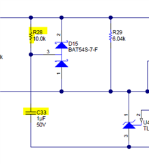
    - For PMP22301, you could adjust R28 to 100k or C33 to 10uF to increase the soft startup time of the dc/dc secondary side.

    - On the LM2596SX side, you could also consider to extend the soft startup time to avoid too high current during inrush. 

    - You could also increase C27 to make dc/dc start later, and the +bus voltage of the FET more stable

    - Could you measure the Vgs of the primary FET at both startup and shutdown? Since the gate pin of TPS23754 was damaged. We want to check if there is any overvoltage.

    Best regards,

    Diang

  • Hi Diang,

    Thankyou for your time.

    Just to clarify, when we reduce the capacitance on the 24V rail, our system works well.

    1. I was able to remove an inductor on the output of the PoE +24V (L6 / J4 in the PMP22301) and power the rest of the system with a lab supply, hence I was able to measure the 100mA current.

    2. Thanks for your suggestions as to changes for soft starting on the PMP22301 design. We will try the resistor change in our next hardware run.

    3. For the LM2596SX designs, we unfortunately can not implement a soft start on the device, and furthermore we are limited in the minimum input and output capacitances per the datasheet.

    4. Our C27 (in the PMP22301 design) consists of 22uF and 2x 1uF capacitors already. We have good stability on this line.

    5. I will have to do a detailed study of the Vgs pin. Our issue is that if we put the capacitance back in the system, we'll damage the TPS23754 device, so it is kind of a one-shot only deal.

    Moreover, I'm actually worried about the mechanism that could cause this issue in the first place. There was another post on this forum where they mentioned removing some output caps from the PMP22301 design to get the device to work. I am wondering if there is something in the feedback path, causing instability with the capacitive loads that ends up oscillating or resonating and damaging the device.

    Is there any mechanism that you know of that could cause the feedback system to function incorrectly with large capacitive loads?

    Thanks

  • Hi Stomp,

    Thanks for your follow up.

    "when we reduce the capacitance on the 24V rail, our system works well." Since you have 24-V output voltage, the energy stored in the capacitor is 0.5*24^2*C, which could be too high (higher than the input capacitator C13's energy in PMP22301). So the PD need drain more current from the PSE, and if it is in the ~80ms inrush period, the hotswap may need to clamp the current and goes into saturation region. This may overheat the IC.

    Best regards,

    Diang  

  • Hi Stomp,

    Since we have not received your update for a relative long time. I will close this thread for now. Please feel free to open a new thread if you have any further questions. Thanks!

    Best regards,

    Diang