This thread has been locked.
If you have a related question, please click the "Ask a related question" button in the top right corner. The newly created question will be automatically linked to this question.
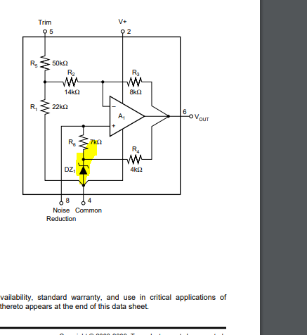
Part Number: REF5010
Hello All,
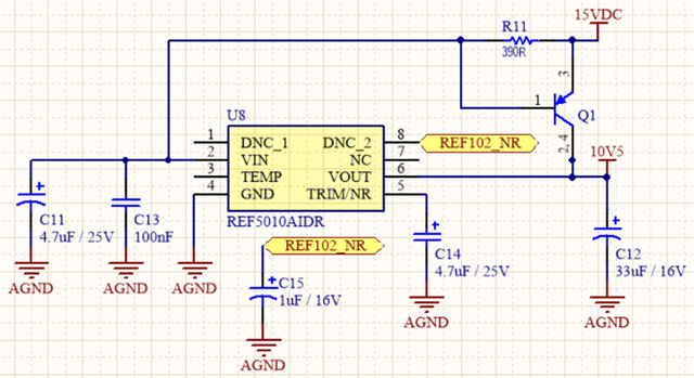
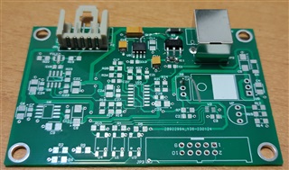
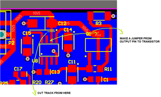
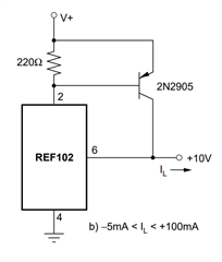
I have a loadcell condition circuit. I have been using REF102A (DIP) and ADR435 IC's. After end of life of REF102 (DIP) I have made a new board using REF5010 and REF5050 pair. For 10V I have been using current boost circuit with a transistor. My maximum current for 10V is around 90mA. When there is no loadcell attached to circuit current consumption can be around 3-5mA. Transistor is BCP53/16.
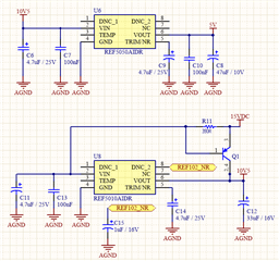
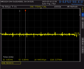
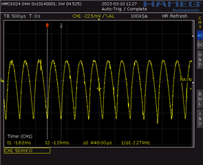
I noticed there is an oscillation on REF5010. There is no problem with REF5050.
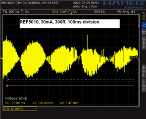
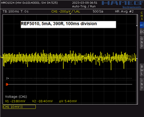
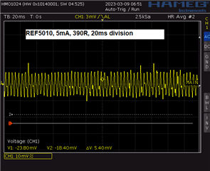
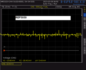
If I increase 390R resistor to 2K ripple decreases but when no loadcell attached circuit (low current) Output of REF5010 becomes Vin, which is 15V. With REF102 DIP I do not have any problem.
Hello,
I have both test it with 22uF / 200mOhm capacitor and 33uF / 1.2 Ohm capacitor. I have built my board. I can both solder REF102BU and REF5010. Normally pin8 is not populated if I want to test REF102BU then I insert C15 and remove C14.
Hi Dogan
Thanks for confirmation . I looked in your circuit in more detail.
You are biaing the circuit with constant current source - I_IN = VEB/R11.
Let's say VEB = 0.6V , When R11 = 2K then I_In = 0.3mA which is < Ibias of the circuit and VOUT is not regulating. At R11 = 390 ohm , VIN has to take around 1.5mA . It means it is forced to give Iout = 0.7mA . Which will affect it's load regulation and circuit will oscillate.
REF102 is a zener (shunt regulator) based topology which can be bioased with constant current source and it will not give issue.
REF50 has to be biased with voltage source.
Can you please confirm this by removing transistor Q1 and shorting R11 . Check the output without any load cell. It should not oscillate.
Usualy people put opamp to drive high current with seriese refernce. I will think and propose some circuit after your confirmation.
REF50 is working fine as it is powered up by voltage source. Let me know your test results and we will discuss further.
Regards
Trailokya
Hello Trailokya,
Yes When I remove transistor and short R11 there is no problem. I also power a REF5050 with REF5010, both of them works nice.
It is strange that I have same problem with REF102BU too.
I have been using REF102AP for more than 10 years now. With various different PCB designs.
Now with my new PCB REF102BU oscillates too. Is layout very critical? transistor is a little bit has more distance from IC with the current design.
Is there a difference between DIP and SOIC package that I need to consider?
I have two different PCBs. Both have identical components and circuit. This boards I solder REF102BU, Bottom one has smaller footprint for capacitors therefore I solder them little weird. Bottom one oscillates and top does not. REF102BU does not have any high frequency circuit I guess. Transistor has more distance with REF102 but It it not that far away.
this is REF102BU with older PCB. 30mA current
this is REF102BU with new PCB. 30mA current
Hi Dogan
I feel the design is not very robust as it is powered up by current source which may create problem fro dynamic load as , any mismatch between output transistor and the REF output may lead to oscillation.
Can you please revise your design with VIN directly powered up with voltage source and buffer. This will not give any problem in future even if you are switching to different design. Let me know if you need any suggestion.
Regards
Trailokya
Hello,
For REF5010 I can understand that.
But for REF102BU, I have been using REF102AP for more than 10 years maybe over 10000 pcbs manufactured. I did not notice such a thing. Of course I did not check every PCB for output of REF102 with 50mV AC. But I have 200 PCBs right now that I can check all of them. If all of them are OK then there must be a layout or SMD version difference issue.
Does texas in. have any application note or similar document to give idea on powering on Vin with voltage source and buffer and also have current boost?
Hi Dogan
We recommend to use high output current opamp in unity gain configuration for this.
Have you checked current transient on all the board.
Can you please tell your accuracy requirement ? We have LM4050 in shunt regulator family which can work with same circuit but it is not P2P.
Regards
Trailokya
Hello Trailokya,
I have two different possibilities, I can have 1 loadcell or 3 loadcell configuration. For 1 loadcell I am using around 35mA, for 3 loadcell around 90mA. There are no components on the PCB. Just Loadcell.
I have tested 40 different PCBs with REF102AP. None of them have such oscillation on output. Why I am getting oscillation with REF102BU. It must be layout related problem.
I have modified PCB a little bit. But nothing changed.
Hi Dogan
Can you please remove C15 in the origuinal board for REF102BU and cahcek once. The data sheet recommends 1000pF as typical cap load. This variant may have issue in driving such a high load cap. Typical application circuit in the data sheet also doesn't recommend any cap load.
Regards
Trailokya
Hi Dogan
I am closing the therad here as we are discussing it in more detail in other forum.
Regards
Trailokya
Hi Dogan
Thanks for all the details. We figured out the problem is comming from C11||C13 as it is introducing an extra pole in the loop and causing the instability. The setup is stable when C11 and C13 are removed.
Good luck with your design.
Regards
Trailokya