This thread has been locked.

If you have a related question, please click the "Ask a related question" button in the top right corner. The newly created question will be automatically linked to this question.

BQ25720: input cap value question

Part Number: BQ25720

Hi team,

I have two quick question about input cap value,

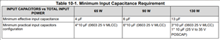
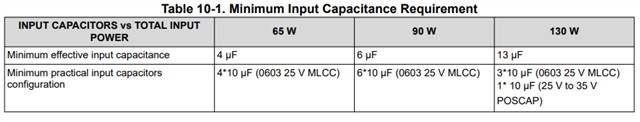
1.why do we need to add extra one POSCAP for high power instead of extra MLCC?

2.what would happen if we have insufficient cap value here,  only large input voltage ripple?

  • Hi Fred,

    1. Because for 130W application it would take too many pieces of MLCC for the recommended capacitance. At that point, space limitation comes into discussion. It makes more sense to start using non-ceramic caps.

    2. Larger input voltage ripple + more EMI due to the huge variation of input + depending on parasitic between AC/DC and charger, higher power stage current

    Thanks,

    Peng

  • Hi Pengzhao,

    thanks you,

    but my question will be why 10uF POSCAP will be more effective than 10uF MLCC?

    I thought MLCC has best response and lowest ESR?

    Regards,

    Fred

  • Hi Fred,

    Because ceramic capacitor's capacitance derates with voltage and polymer cap typically does not. In other words, for a single polymer cap of 10uF, you may need a ton of ceramic caps to give you the same equivalent capacitance for a certain applied voltage. When you have to add so much MLCC to your board, then board size becomes the product limitation.

    For reference, you can check out datasheets of any ceramic and electrolytic caps online. Pretty much any cap you find online will show this characteristic. The same info is also available on the datasheet on "10.2.2.3 Input Capacitor", and is available on the first paragraph above the table you shown.

    Thanks,

    Peng

  • Hi Pengzhao,

    DC bias , note it.

    appreciate a lot.

    last question, should we place POSCAP in 100W design?

    or it depends on parasitic at input in every design?

  • Hi Fred,

    For 90W, we recommend minimum effective input capacitance of 6uF. For 100W, I would start with ~8uF.

    Whether or not to add a POSCAP really depends on their board limitation and their application. If they can get around ~8uF minimum effective capacitance across all operating condition (any combination of POSCAP + ceramic), I think they are in a good place to start. Of course, it doesn't hurt to have backups by having unpopulated footprints.

    Thanks,

    Peng