This thread has been locked.

If you have a related question, please click the "Ask a related question" button in the top right corner. The newly created question will be automatically linked to this question.

BQ40Z50-R2: Help reviewing Schematic for battery monitoring system

Part Number: BQ40Z50-R2

Hello,

This design is based off of the the reference design for the bq40z50EVM, but meant to only collect data on the state of the connected cells.

I have previously had sucessful communications with the host device and the EV2400 interface adapter using the BQ40Z50EVM evaluation module.  
However when I test my own implementation with these tools the BMS is not discoverable on the bus and I am unable to receive any replies when commands are issued to it.

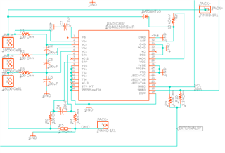
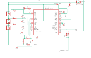
below is an image of my schematic. Any ideas why it would not be communicating?


  • Hello Andrew,

    CHG and DSG pins should not be tied to ground if not used. Output pins should be left floating. Also your cell voltage capacitors seem to be quite high. VCC should be connected to the system side power (essentially same node as BAT without the gauge protection FETs). I would also probably tie the PACK pin to the PACK+, not to the BAT node.

    Sincerely,

    Wyatt Keller

  • would this edited schematic be what you are describing.

  • Hello Andrew,

    Please use the EVM as a guideline for your connections, after looking over it again your ground reference for the gauge seems to be on the incorrect side of the sense resistor, also C4 appears to be polarized, it should be a non-polarized capacitor.

    Sincerely,

    Wyatt Keller