


Hello Team,
As I read in the data sheet, the CS pin is typ. 356mV with constant current regulation.
During a measurement I noticed that the voltage is up to 750mV with constant current regulation, as you can see in the following picture.
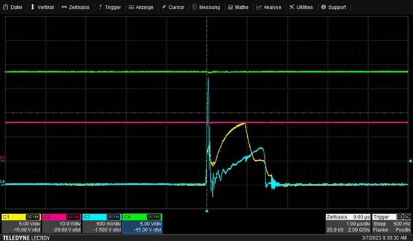
The voltage at the CS pin is shown in blue.
Yellow = DRV-Pin (MOSFET gate)
Red = Vdd Pin
Green = 24V output voltage

I am using a circuit as described in the datasheet with the following values:
- Cdd = 12µF
- Rs1 = 100k
- Rs2 = 31k8
- Rcs = 1R5
- Rcl = 560R
The output voltage is 24V and the output current is 250mA.
- Is there an explanation for the higher voltage on the CS pin?
Because of the high current through the current-sense-resistors (and transformer) I have a problem with saturation of the transformer.
Additionally I have a problem with saturation at the startup. The voltage at the current sense pin rises up to over 1 V as you can see in the picture below.
The voltage at the CS pin is shown in blue.
Yellow = DRV-Pin (MOSFET gate)
Red = Vdd Pin
Green = 24V output voltage
Thanks,
SunSet
