This thread has been locked.

If you have a related question, please click the "Ask a related question" button in the top right corner. The newly created question will be automatically linked to this question.

TL494:TL494 FB端子へのコンデンサの使い方

Part Number: TL494

ある基板回路において、TI製TL494CNSRを使用しております。

FB端子へのコンデンサの接続について教えていただけないでしょうか。

FB端子へのコンデンサ.xlsx

ある基板回路において、TI製TL494CNSRを使用しております。

設計担当者が既にいらっしゃらないので、質問させていただきたいですが

下記の点について教えていただけないでしょうか。

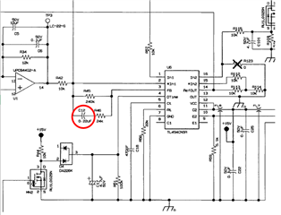
データシートを確認しましたが、FB端子へのコンデンサの接続については

記載が無いようでした。よろしくお願いいたします。

1.上回路図でFB端子に(抵抗+セラミックコンデンサ)を接続しておりますが

回路の構成でコンデンサを挿入することは間違っていないでしょうか?

2.コンデンサと挿入接続しているのは、どういった理由で入れるのでしょうか?

3.コンデンサの容量(0.22uF)は適切な値でしょうか?

  • Hello,

    I am not sure where this schematic is coming from so will try to answer your questions as best I can without any background.

    1. 上回路図でFB端子に(抵抗+セラミックコンデンサ)を接続しておりますが

    回路の構成でコンデンサを挿入することは間違っていないでしょうか? An RC connected like this in parallel with the feedback resistor is usually intended to help improve the dynamic response. The capacitor works as a DC blocker so will only pass dynamic changes.

    2.コンデンサと挿入接続しているのは、どういった理由で入れるのでしょうか? It was likely added to improve the transient response of the circuit.

    3.コンデンサの容量(0.22uF)は適切な値でしょうか? It is hard to say without understanding more background for the circuit and the design goals. The size of the capacitor will be directly proportional to the amount of current injected into the FB pin based on whatever ripple is seen at IN1. If it is too small it will have no impact. If it is too large it may have more impact than you would like. 

    I hope this helps, but without more details, it is hard to answer exactly.