This thread has been locked.

If you have a related question, please click the "Ask a related question" button in the top right corner. The newly created question will be automatically linked to this question.

TUSB1064: AUX signal eye diagram was decreased due to TUSB1064

Part Number: TUSB1064

To whom it may concerns

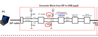
we are designing the alternative mode by USB type C.

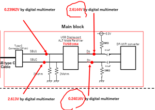
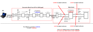
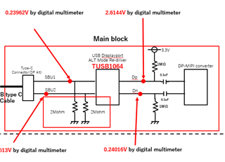
and we are using TUSB1064.

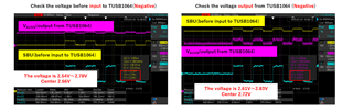
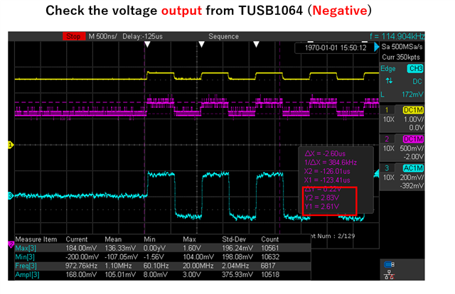
the Link Training is failed sometimes. so, we checked the waveform for Aux positive and negative by differential probe.

we noticed that the waveform was decreased after pass through TUSB1064.

I attached the waveform.[Problem] decrease the swing of AUX after pass through TUSB1064.pptx

could you tell me how to minimize the decreasing the eye diagram for AUX by TUSB1064?

and please tell me whether we can increase the AUX signal or not.

Best Regards,

Y.Nakanishi

  • Y.Nakanishi-san

    TUSB1064 AUX/SBU is a passive switch and does not control or drive AUX signal amplitude. Can you please measure the common mode voltage of the AUX/SBU bus? They need to follow the TUSB1064 spec as shown below.

    Thanks

    David

  • dear David-san

     thank you for your reply.

    I measured the AUXP and AUXN , SBU1,2.

    please check the waveform.

    is the spec is DC voltage?

    if so, the Negative side seems slightly lower than spec...

    could you check the attached file and please give us advice.

    [Problem] decrease the swing of AUX after pass through TUSB1064_rev2.pptx

  • Y.Nakanishi-san

    The single-ended AUXN measurement uses different vertical scale per division, so I can't tell if there is an issue with the AUX itself. 

    But with the common mode voltage being correct, then the SBU/AUX switch should work. It is a passive switch without any signal compensation. But 348mV differential peak to peak voltage is above the 270mV per the DP spec, is there an particular issue with the 348mV differential peak to peak voltage?

    Thanks

    David

  • > he single-ended AUXN measurement uses different vertical scale per division, so I can't tell if there is an issue with the AUX itself. 
    Ops, I'm very sorry, How should I show the waveform?

    I just check the voltage comparing to spec. I suspect the AUX_N is little bit low... 
    but if the range is out of working area, the output should be nothing. in this case, sitll the TUSB1064 is working properly.

    our problem is 

    the amplitude is reduced after pass through TUSB1064.

    due to drive capability of laptop, the 348mV become less than 270mV when reach to DP-MIPI converter IC.

    so, DP-MIPI converter IC can not reply to Source devices sometimes. 

    I'd like to avoid reducing amplitude due to TUSB1064 although we can not increase the amplitude.

    Best Regards,

    Y.Nakanishi

  • Y.Nakanishi-san

    You can measure the common mode voltage of AUXP and AUXN using a multi-meter. 

    Is it possible that you can share your schematic and layout?

    Thanks

    David

  • David-san

    I added the circuit diagram in ppt.

    and I key in the voltage for SBU1, 2 and AUX P and N which I measured by multimeter.

    please check it.

    [Problem] decrease the swing of AUX after pass through TUSB1064_rev3.pptx

  • Hi,

    Do you have the 100k pullup/pulldown populated correctly on the TUSB1046 side? As you can see from the TUSB1064 common mode measurement, the common mode voltage is outside TUSB1064 spec.

    Thanks

    David


  • David-san
     sorry, too late my reply.

    as I show by power point before, we put 100kohm as above figure.

    I also mentioned in power point slide regarding the voltage.

    please refer to below.


    BTW, do you have solution to increase the swing voltage at sink device side?

    if we can find this kind of solution which can be increase swing voltage for AUX, we can achieve the DP spec.

    Best Regards,

    Y.Nakanishi

  • Y.Nakanishi-san

    Source 100k pulldown on AUXP is a strong pulldown, so the expected voltage on AUXP is 0.3V. Source 100k pullup on AUXN is a strong pulldown, so expected voltage is 3V. But your measurement shows the AUXP/AUXN voltage does not meet the spec, this is why I ask if 100k pullup/pulldown is being properly populated.

    The AUX swing voltage has to be increased by the source.

    Thanks
    David


  • David-san

    thank you for your quick reply.

    as below figure,

    the 100kohm is in our converter block and it is after TUSB1046.( it is NOT TUSB1064)

    we asked TI member to review the circuit at that time.

    However, do I need to put 100kohm before or after TUSB1064?

    please give me advice.

    The AUX swing voltage has to be increased by the source.

    regarding this point, 

    I checked the swing level by several PC. the level is different among each PC.

    I understood that the swing level is depending on PC. 

    even if Sink side can request to Source, the swing level is limited or essentially Sink can not send request to Source since Sink can not receive AUX communication.

    it is my analysis result .

    do you have any comment about this consideration ?

  • Hi,

    Your physical AUX implementation is correct.

    For TUSB1046,

    1. 100k pulldown on AUXP

    2. 100k pullup to 3.3V on AUXN

    For TUSB1064

    1. 1M pullup to 3.3V on AUXP

    2. 1M pulldown on AUXN

    But your AUXP/N measurement does not match with the AUX implementation. I would expect to see 0.3V on AUXP and 3V on AUXN. So you need to check whether the 100k is being populated correctly on the TUSB1046 side since 100k is a stronger resistor than the 1M resistor or you need to check your FLIP pin, make sure the FLIP pin is being driven correctly.

    Thanks

    David

  • David-san

     sorry, too late my reply.

     because we took national holiday in Japan.

    could you tell me how to  check the 100kohm and FLIP pin?

    and you said below

    > For TUSB1064

    > 1. 1M pullup to 3.3V on AUXP

    > 2. 1M pulldown on AUXN

    but I concern that we put 2Mohm pull down before TUSB1064. 

    could you give me comment about 2Mohm pull down ?

    and sorry, I asked to you about below.

    >> BTW, do you have solution to increase the swing voltage at sink device side?
    >> if we can find this kind of solution which can be increase swing voltage for AUX, we can achieve the DP spec.
    > The AUX swing voltage has to be increased by the source.

    you means that the swing level is adjust by source side after communicate with Rx, don't you ?

    However, the swing level is limited by source .  some source is low driven power.

    and some customer want to use long cable. in this case, the swing level become low.

    if you can propose IC to increase swing level for AUX, could you tell me it?

    Best Regards,

    Y.Nakanishi

  • Y.Nakanishi-san

    The 2MΩ pull-down resistors on SBU1 and SBU2 are representative of the leakage of ESD and EMI/RFI components including termination to ensure no floating nodes, and are intended to show compliance with zSBUTermination in USB Type-C r1.0.

    You have a stronger 100k pullup/pulldown on the source side (TUSB1046) while have weaker 1M pullup/pulldown on the sink side (TUSB1064). So the common mode voltage is mainly driven by the 100k pullup/pulldown resistors. Right now, your common mode voltage is not correct on AUXP/N per your multimeter measurement. You need to resolve it first. Once you resolve the common mode voltage issue, then you can check to if the AUX swing voltage is meeting the spec or not. The source needs to increase its AUX swing voltage if it is too low, I am no aware of another solution. 

    You can measure the voltage on FLIP pin for both the normal and flip USB Type-C orientation, and you can visually check to see if 100k pullup/pulldown is populated on the source side.

    Thanks

    David 

  • David-san

     I checked the voltage of FLIP Pin. and just in case, I check CTRL 0/1 also.

    FLIP pin : 3.4384V

    CTRL0 : 0V

    CTRL1 : 3.4385V

    I think the voltage of FLIP pin is no problem.

    do you have comment?

    and could you tell me what was your esitmation ?

    Best Regards,

    Y.Nakanishi

  • [Problem] decrease the swing of AUX after pass through TUSB1064_rev4.pptx

    David san

    sorry, moreover from above message,

    let me update the information.

    I measured swing voltage level for each section of AUX.

    please refer to ppt slide and give us comment.

    I'd like to share /ask by the slide that

      1. whether the swing level of 100kohm is ok or not

       2. the swing level is difference depending on source device.


    in order to avoid missing message by you,

    let me repeat above message in below.

    ********************************************************************************

    I checked the voltage of FLIP Pin. and just in case, I check CTRL 0/1 also.

    FLIP pin : 3.4384V

    CTRL0 : 0V

    CTRL1 : 3.4385V

    I think the voltage of FLIP pin is no problem.

    do you have comment?

    and could you tell me what was your estimation?

    ********************************************************************************

    Best Regards,

    Y.Nakanishi

  • Y.Nakanishi-san

    1. The common mode measurement between the multi-meter and scope does not align with each other. So you need to resolve the difference between the two measurements

    In your scope measurement,

    AUXP common mode voltage is around 0.12V but your multi-meter measurement shows 2.6144V.

    AUXN common mode voltage is around 2.72V but your multi-meter measurement shows 0.24016V.

    2. This particular scope measurement seems to show some noise issue with AUXN, can you double check and make sure it is a setup issue?

    3. Assume the common mode voltage is correct, there will be some amplitude loss. But the only way to compensate the loss is to increase the source AUX amplitude.

    Thanks

    David