This thread has been locked.

If you have a related question, please click the "Ask a related question" button in the top right corner. The newly created question will be automatically linked to this question.

TPS92200D2EVM: About the value of Rfb

Part Number: TPS92200D2EVM
Other Parts Discussed in Thread: TPS92200D1EVM, TPS92200,

Dear TI team

I have a question related to the content of the thread below.

https://e2e.ti.com/support/power-management-group/power-management/f/power-management-forum/1019632/tps92200d1evm-what-is-the-function-of-rfb-how-to-design-the-value?tisearch=e2e-sitesearch&keymatch=TPS92200%25252525252520FB#

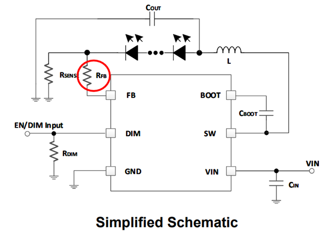
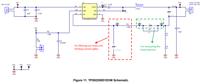
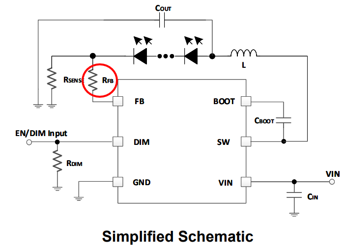
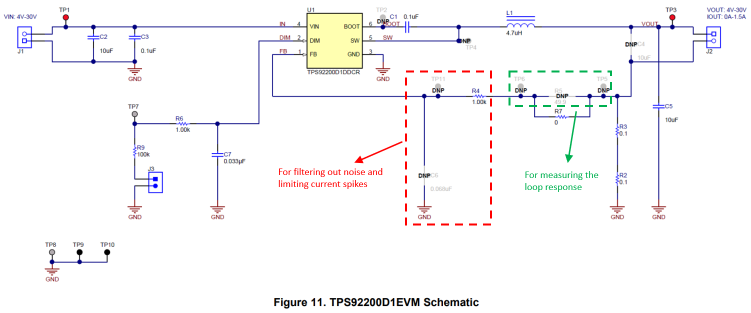
The link above says that Rfb is used to measure the loop response and can be replaced by 0Ω if the loop is not being measured.

If RFB is not used (RFB = 0Ω), is there any possibility that the noise immunity will decrease? (Or could it cause other problems?)

Also, 1.00kΩ (R4) is implemented on the EVM, but how is this value determined?

Best Regards,

Taroimo

  • Hi Taroimo,

    I am out of office today. I will have a check on this thread and reply to you tomorrow.

    BR, Steven

  • Hi Steven,

    Thank you for your reply.
    How is the progress going?

    Best Regards,
    Taroimo

  • Hi Taroimo,

    Sorry for missing this thread. Let me have a check now.

    BR,

    Steven

  • Hi Taroimo,

    The R_FB resistor (which is marked with red circle in the below picture) is used to

    1. limit any current spike into the FB pin
    2. form a low pass-filter together with the parasitic capacitance of the FB pin and therefore filter out some noise

    Normally the value of R_FB is selected based on test results.

    Best Regards,

    Steven

  • Supplement:

    For the old post you mentioned, I still need to double check it with some senior experts in our team about its correctness. I will let you know the results once we have a result.

  • Hi Taroimo,

    I have a discussion with a senior expert from our team. The result is that my answer and the former answer (the old post) are both correct.

    In our EVM (let's take TPS92200D1EVM as an example), we use two sets of resistors for different purposes, as is shown in the below picture.

    Best Regards,

    Steven

  • Hi Steven,

    Thank you for your confirmation.
    Summarizing, including the contents of the previous thread, is the following understanding correct?

    ① There is no problem with "RFB = 0Ω".
    ② It is recommended to implement an RFB resistor in the kΩ range to filter input noise into the RFB pin and limit current spikes.

    Best Regards,
    Taroimo

  • Hi Steven,

    Since the noise level and parasitic capacitance are different for each system, we understand that it is necessary to check the RFB value on the actual system for each design.

    However, I do not know how much resistance is allowed, so please let me know. (If the resistance value increases, it is effective for noise reduction, but the signal level drops, so I am worried about how much resistance value I should select.)

    I understand that the input impedance of the FB pin is large enough, but I would like to know how large a resistance value is acceptable. (Or do you have some sort of guidelines for designing?)


    Best Regards,

    Taroimo

  • Hi Taroimo,

    1. RFB = 0 ohm is ok if there is not any noise problem at your FB pin.
    2. The resistor value is based on your actual circuit and varies from condition to condition. I have seen values like ~1kohm or ~500ohm, but that may not fit your application.
    3. Our recommendation is to place footprints for an RC filter in your prototype PCB (as is shown in the red dashed-line box above). And if there is any noise problem at the FB pin during the test, you can measure the noise frequency and design an RC filter for it. The resistance should not be too large. Otherwise, the feedback accuracy will be affected.

    Best Regards,

    Steven

  • Hi Steven,


    Thanks for the very quick reply.

    After all, I understood that it is useless if the resistance value is too large.

    We consider footprints from 500Ω to 1kΩ for Rfb.


    Best Regards,

    Taroimo

  • Hi Taroimo,

    You are welcome.

    I will post a summary below for those who may have the same question. Please kindly help click "This resolved my issue" button to make the post stand out, so that it can be easily found by others.

    Later I will close this thread. Feel free to contact me again if you have any further question.

    Best Regards,

    Steven

  • Summary:

    For TPS92200, the R_FB resistor (which is marked with red circle in the below picture) can serve two purposes.

    1. R_FB can limit current spikes into the FB pin, and also form a low pass-filter together with the parasitic capacitance of the FB pin and therefore filter out some noise. Normally the value of R_FB is selected based on test results. It can be 0 ohm if there is not any noise problem at the FB pin in your application.
    2. R_FB can be used to measure the loop response. It can be 0 ohm if you don't measure the loop response.

    We reserve places for these two purposes on TPS92200 EVM, as is shown below (let's take TPS92200D1EVM as an example).

  • Hi Steven,


    Thanks for the summary.

    This has cleared up a lot of points, but for those of you who have the same question, please let me know a little more.

    (I would like to click "This resolved my issue" as soon as the following contents are clear.)


    ① Is it possible that increasing the CFB value too much will have adverse effects such as unstable IC output?

      (If the capacitance is too large, the phase delay will increase, and I am concerned that the phase margin will be insufficient and the operation will become unstable.)

    And if so, to what extent is it possible to increase the CFB value?


    ② In the end, the reason why 1kΩ is placed on the RFB on the TPS92200D2EVM (a certain thing such as a calculation formula) is a recognition that has not been shown.

    I understand that the reason for this is that even during the EVM design of this IC, the appropriate resistance values were selected through cut-and-try based on the actual circuit. Is this correct?

    (Because, as with many other examples, the parasitic capacitance and noise level are unknown during EVM design until they are evaluated.)


    I have a request below, but I would like to see more guidelines for determining the RFB value in the device datasheet and EVM user guide. (Example: When the parasitic capacitance is XpF, it is better to set the first RFB value to YΩ, etc.)

    I am fully aware that it is difficult to give a general answer as the conditions differ depending on the system.

    Still, all designers should be happy if there is a description.


    Best Regards,

    Taroimo

  • Hi Taroimo,

    Of course. I am willing to continue the talk to provide more details for those who comes here later.

    1. For which C_FB do you refer to? Do you refer to the 'C6' on the TPS92200D1EVM? If this is the case, then a too large C_FB value will have adverse effects such as an unstable current output. Still, it is hard to give an exact extent for C_FB value. One method is to measure the loop response, verify if it is appropriate and adjust accordingly.
    2. We do not have any formula for R_FB (The only one may be the normal RC low-pass filter formula). The value depends on the test results. I am not sure what happened during the design of this EVM as I cannot find the designer at that time. But my recommendation is that in your prototype PCB build, you can leave the place for the RC filter at first, then try and test.
    3. Thanks for your advice. We will take that into consideration when later writing device datasheet / EVM User's Guide.

    Best Regards,

    Steven

  • Hi Steven,


    Thank you for your detailed review.


    The CFB I mentioned refers to the "C6" of the TPS92200D1(D2)EVM as you indicated.

    It turns out that the output becomes unstable when the value of CFB is too large.

    I understand that the design should be started as unimplemented for CFB so that the value set in the preset does not cause problems.


    I also learned that it is important to check the loop response in the actual system.

    So I would like to know how to measure the loop response in EVM.

    (Regarding modifications such as cutting traces/patterns on the EVM, points to note when measuring, etc.)

    Since this is different from the content of this thread, I will create a new thread.


    Best Regards,

    Taroimo

  • Hi Taroimo,

    You are welcome. Let's continue the talk on the other thread.

    Another comment here for your reference: I just find Section 9.2.1.2.4 FB Pin RC Filter Selection and Section 9.2.2.2.4 FB Pin RC Filter Selection from TPS54200 datasheet could be a good start point for you to select the RC filter. But as I have mentioned, the final selection needs to be tested and may need to be iterated based on the test results.

    BR,

    Steven